[0012]With the novel tempering channel and method of operating it, it is possible to use the part of the conveyor belt being located directly downstream of the transfer location of the tempering channel as seen in the direction of movement of the conveyor belt for positively influencing the confectioneries with respect to temperature, and especially the bottom of the confectioneries. It is possible to eliminate a great number of influencing factors in a way that depending on the kind of confectioneries not only the tempering tunnel but also the entrance zone already beginning downstream of the transfer location is used for tempering in an advantageous way.
[0016]The novel method has a number of advantages. It makes use of a portion of the conveyor belt downstream of the transfer location and of the entrance zone which may be characteristic in a way not to stop or to negatively influence the treatment of the confectioneries with respect to temperature at this place. Coordination with the temperature profile of the tempering apparatus in the tempering tunnel is possible. For example, in this way, it is possible to partly discharge the tempering tunnel. In special cases, this may have the positive effect of making it possible to reduce the length of the tempering channel and not having to use a tempering tunnel at all. The different temperatures of the conveyor belt more or less accidentally occurring after its exit from the tempering tunnel are compensated by heating and / or cooling of the lower part of the conveyor belt. The novel method may be used no matter whether the lower part of the conveyor belt is located in the cooling tunnel or below the cooling tunnel, especially in the atmosphere surrounding the cooling tunnel.
[0018]The novel method and the novel tempering channel make it possible to manufacture high-quality confectioneries, especially such ones including a bottom coating. In this way, for example, the crystallization process as beginning in the tempering machine and which should be continued in the coating machine located downstream and in the cooling tunnel are not interrupted or negatively influenced in the beginning portion of the cooling channel outside of the cooling tunnel. Instead, one attains a continuous process of crystallization of chocolate mass, for example. Due to the optimal temperature of the conveyor belt in the region of the transfer location immediately having an effect during first contact with the arriving confectioneries, the crystal structure is improved with respect to quality. This results in additional advantages, for example surface gloss, better gripping properties of the confectioneries, and the like. Additionally, migration of fat through the bottom coating of the confectioneries is reduced, for example. The optimal constant temperature to be attained at the transfer location depends on many factors such as the moving velocity of the conveyor belt, the length of the tempering tunnel and of the tempering channel, the temperature in the tempering tunnel, the number of products on the conveyor belt, room temperature, and so forth. The optimal temperature being coordinated with the respective case of application prevents a wrong constant temperature, as it more or less accidentally occurs when operating the tempering tunnel. This is of great importance for some products. The novel tempering channel for confectionery articles is generally based on tempering channels as they are known in the prior art. In most cases, such a channel includes a tunnel being formed by a series of covers and at least covering a great portion of the length of the channel. In addition, there may be an entrance zone of the tempering channel in which no tunnel section is located.
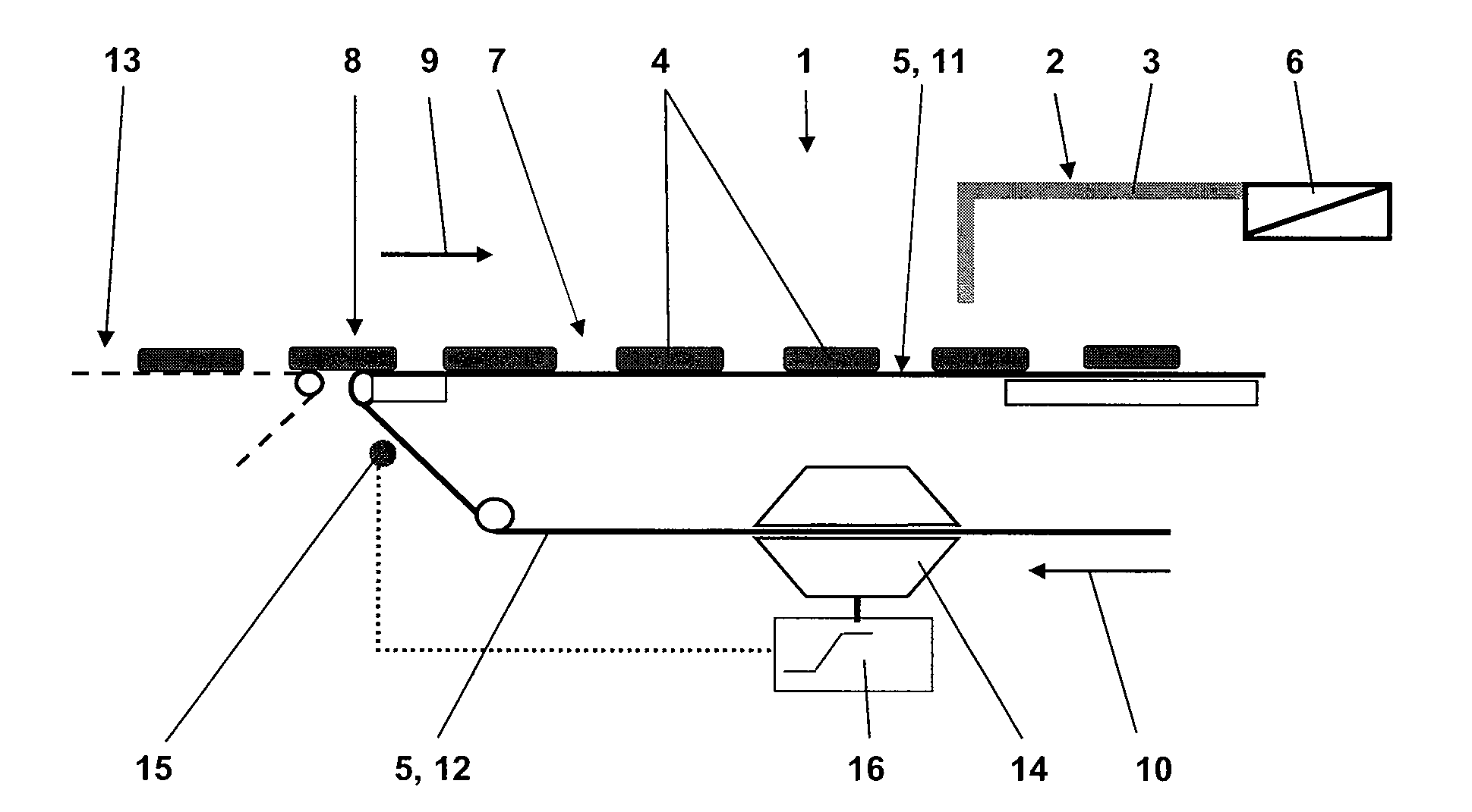
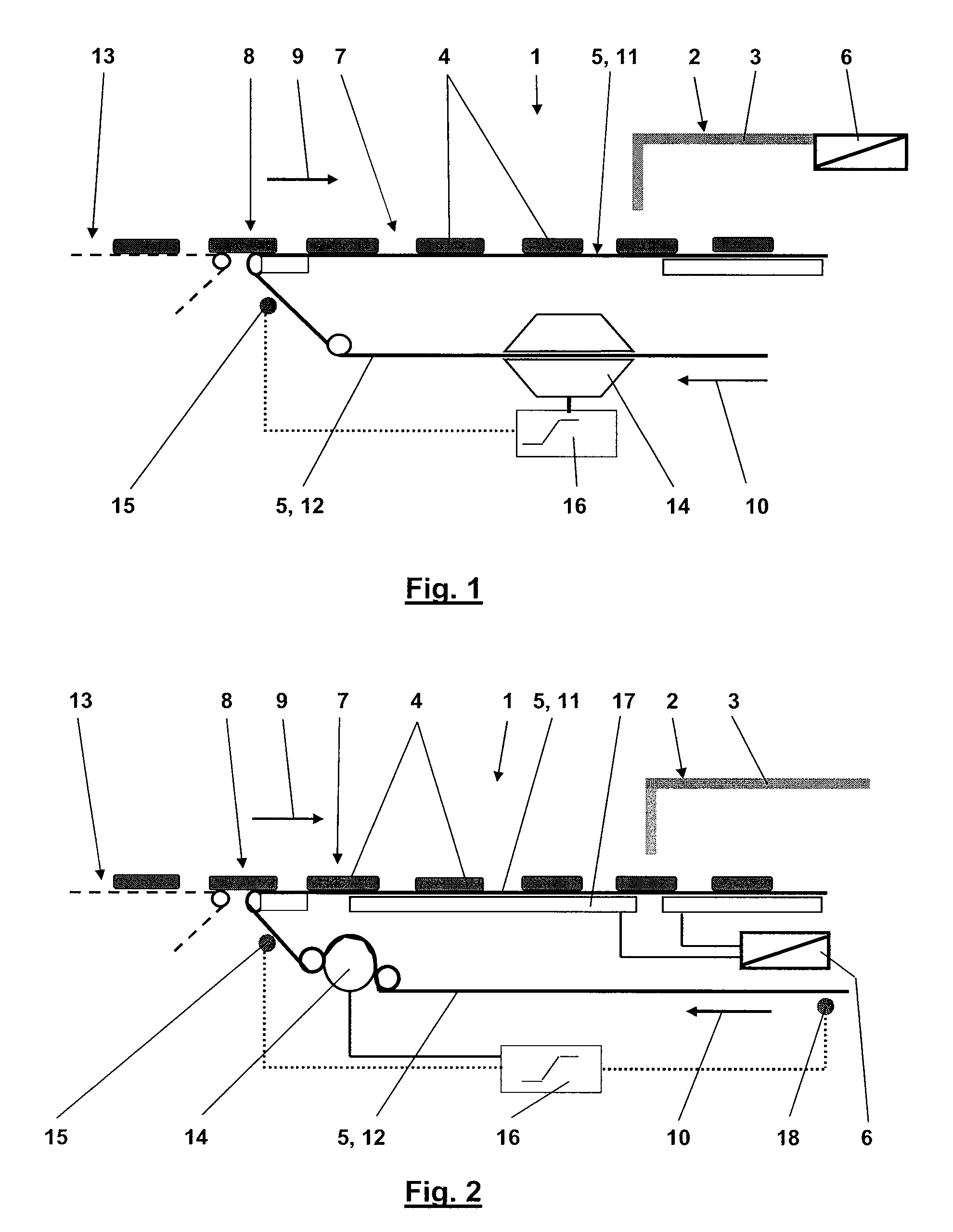
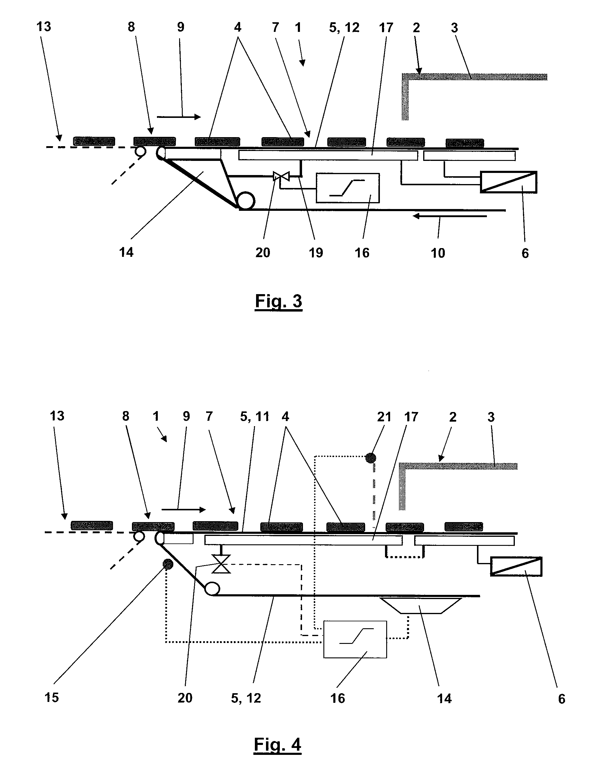
[0019]In all cases, there is a transfer location for the arriving confectionery articles. The transfer location may be formed by a deflecting roller having a comparatively small diameter or even by a knife edge. This serves to make it possible to securely move comparatively small confectionery articles from the machine located upstream onto the conveyor belt of the tempering channel. The tempering tunnel of the tempering channel includes a first tempering apparatus serving to directly influence the temperature of the confectioneries placed on the conveyor belt in the desired way as they are located in the tunnel. However, advantageous tempering of the confectioneries in the tunnel does not necessarily mean that this is also positive for the temperature of the conveyor belt as it is moved through the tunnel. Instead, this temperature may lead to a temperature prevailing at the transfer location which is disadvantageous for the respective confectionery product.
[0020]Thus, the novel tempering channel now includes an additional tempering apparatus being designed and arranged to directly influence the temperature of the lower part of the conveyor belt. The lower part of the conveyor belt is heated and / or cooled in a way that the conveyor belt at the transfer location has an optimal temperature being coordinated with the confectioneries. The optimal temperature may be chosen in a way to attain a more or less constant temperature of the respective confectioneries during their movement between the machine located upstream and the tempering taking place in the cooling tunnel to optimally process the confectioneries along the entire way. In this way, a possible temperature difference of the conveyor belt at the beginning of the lower part of the conveyor belt may be compensated.
[0021]The conveyor belt is at least partly made of plastic. The plastic may be in the form of plastic film or plastic filaments forming the conveyor belt, for example in a woven way. In this way, the conveyor belt may have a structured surface such that the bottom parts of the confectioneries attain this structure. A closed bottom surface, preferably without air bubbles or the like is a quality feature of coated confectioneries. This advantageous effect may be realized by the present invention.

