Dual panel fabrication

a technology of dual panels and fabrication methods, applied in the direction of dryer section, dryer machine with progressive movement, soldering auxiliary devices, etc., can solve the problem of correspondingly higher factory and manufacturing costs therefor

Active Publication Date: 2011-11-15
THE NORDAM GRP
View PDF7 Cites 1 Cited by
  • Summary
  • Abstract
  • Description
  • Claims
  • Application Information

AI Technical Summary

Problems solved by technology

Multiple panel presses are typically used in a factory for manufacturing many laminated panels in large bulk quantities, and increasing the number of manufactured panels requires more panel presses, with correspondingly higher factory and manufacturing costs therefor.

Method used


Image

  • Dual panel fabrication
  • Dual panel fabrication
  • Dual panel fabrication

Examples


Embodiment Construction

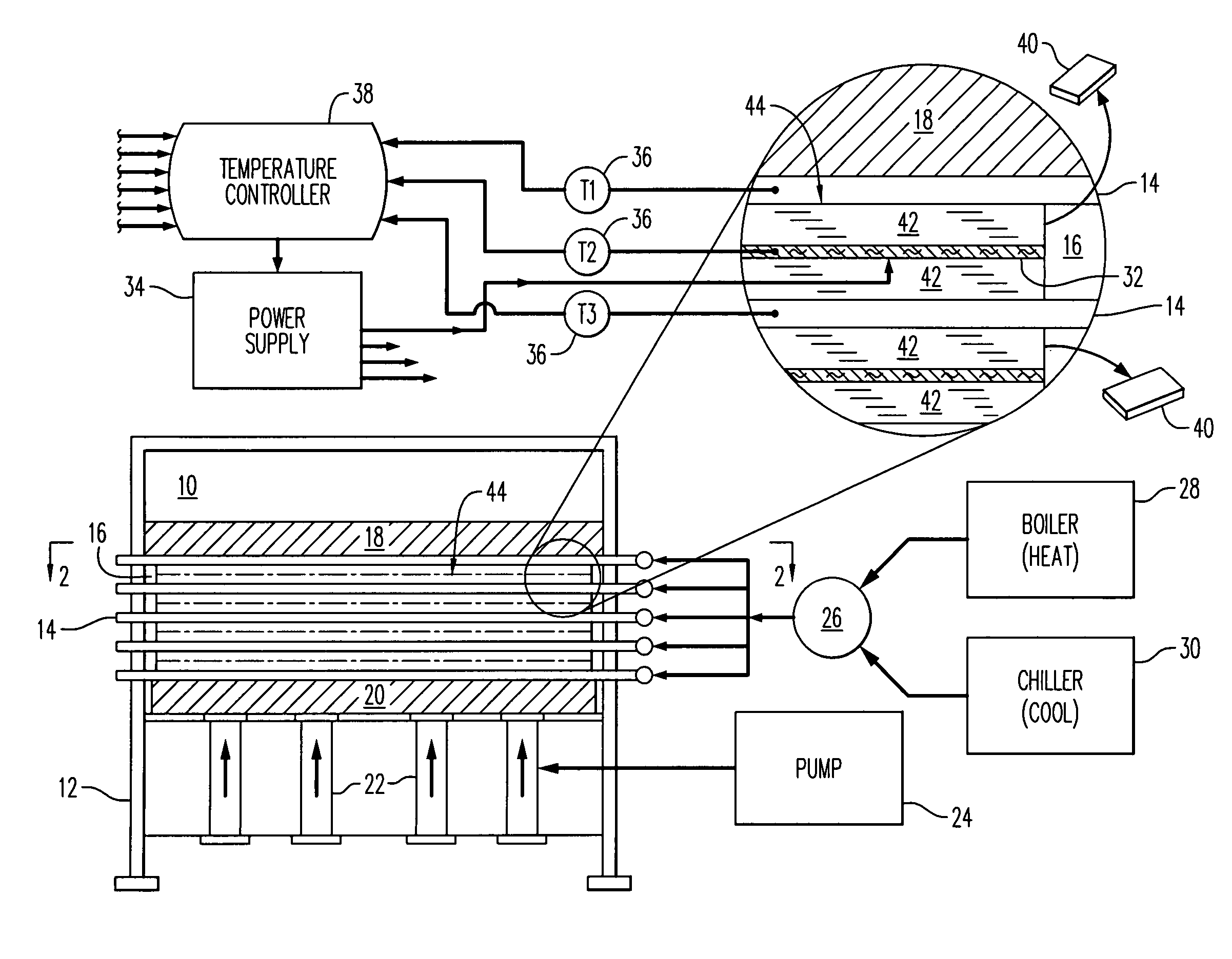
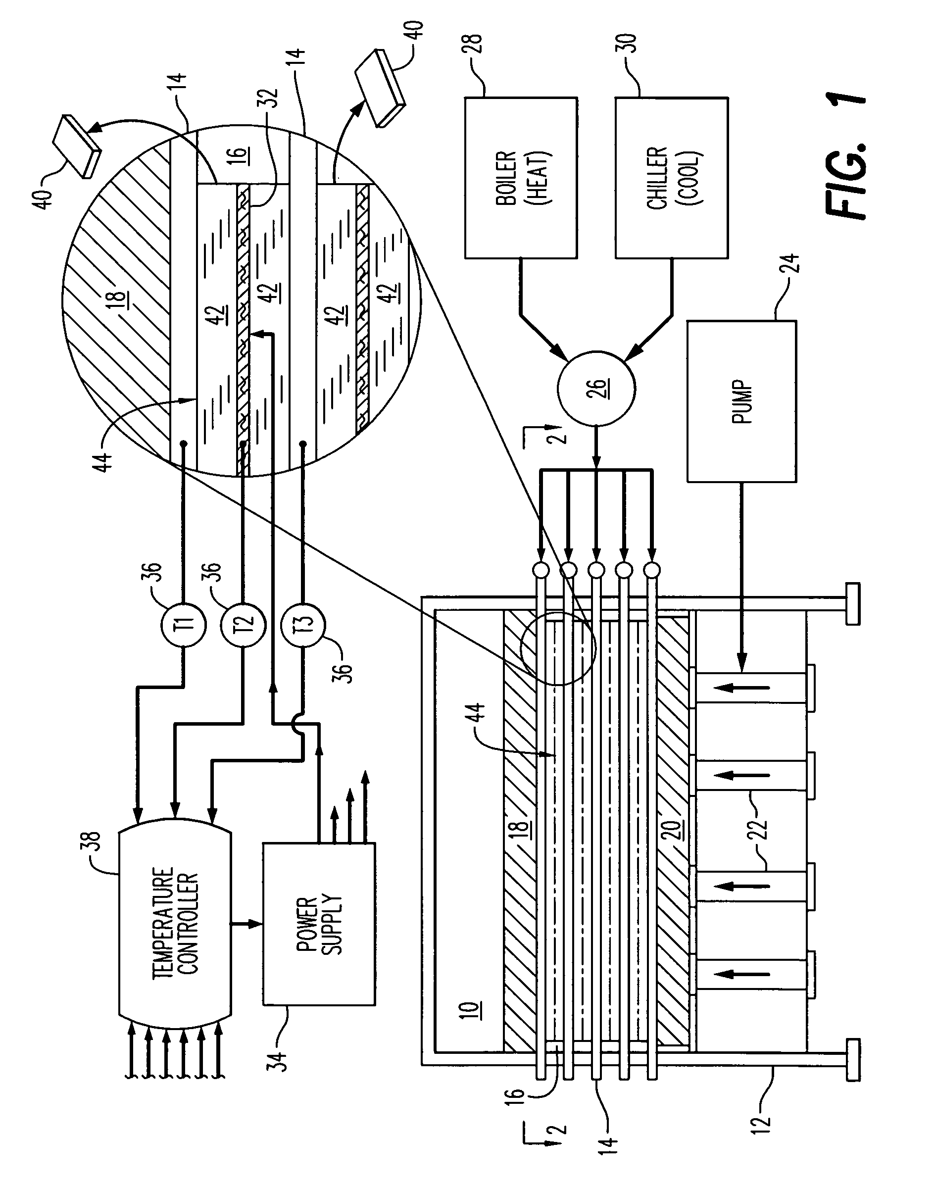
[0024]Illustrated schematically in FIG. 1 is a hydraulic panel press 10 having a suitable structural frame 12 for supporting its various components.

[0025]In particular, the press 10 includes a plurality of flat rectangular platens 14 suitably mounted or affixed in an adjustable vertical stack in the press frame 12. Adjacent ones of the several platens 14 define vertically therebetween corresponding chambers or slots 16. For example, five platens are illustrated in the exemplary press machine 10 and define four corresponding receptacle slots 16 therein

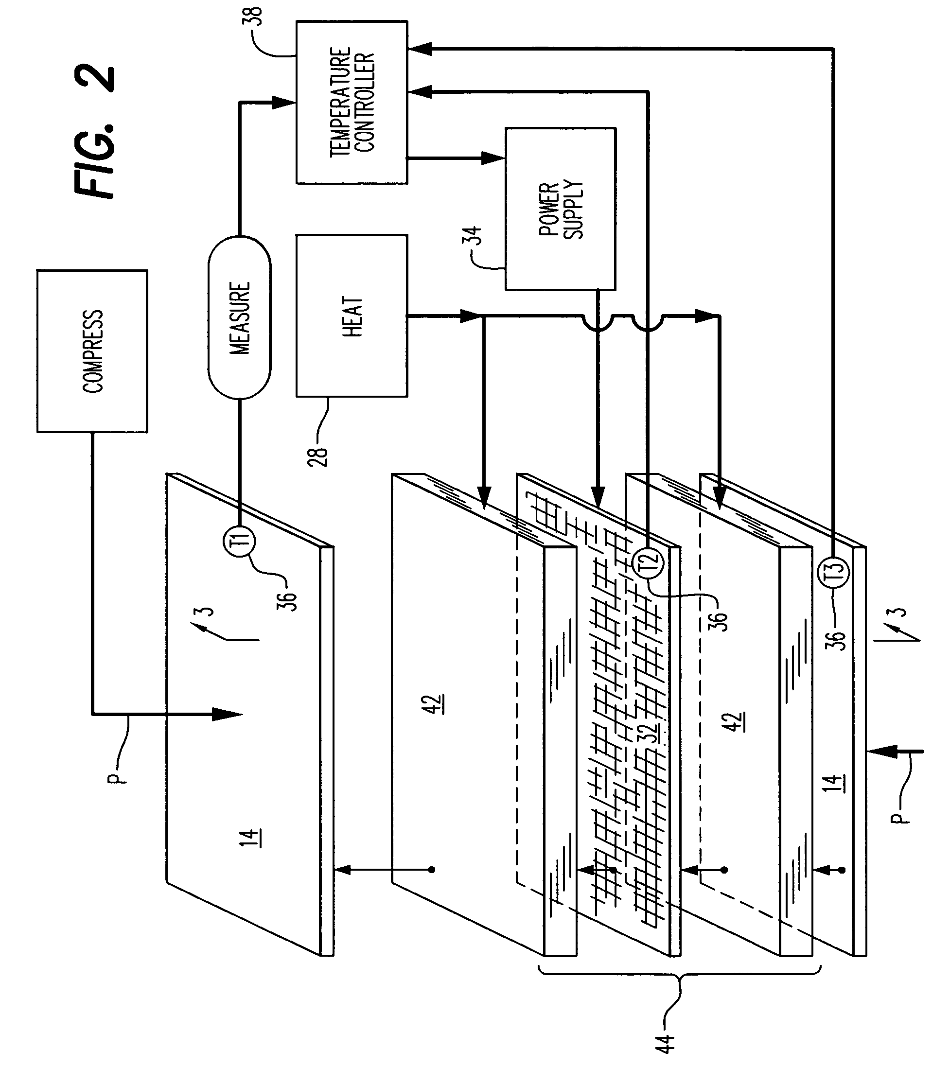
[0026]The panel press 10 further includes a structurally rigid anvil 18 in the form of a thick rectangular plate 18 fixedly joined to the frame 12 at the top thereof. At the opposite bottom of the frame 12, a structurally rigid wedge 20 in the form of another thick rectangular plate is mounted in the frame atop a plurality of suitable piston actuators 22, with four being illustrated for example.

[0027]The actuators 22 are in the exemplar...


PUM

PropertyMeasurementUnit
compression pressuresaaaaaaaaaa
thickaaaaaaaaaa
thickaaaaaaaaaa

Abstract

A pair of laminated panels are simultaneously manufactured in a single panel press. A thermal band is stacked between two panel sets and then the two panel sets are simultaneously heated and compressed together in a common stack with the band, with the band being separately heated.

Description

[0001]This application claims the benefit of U.S. Provisional Application No. 61 / 002,477; filed Dec. 9, 2007.BACKGROUND OF THE INVENTION[0002]The present invention relates generally to manufacturing processes, and, more specifically, to laminated panel fabrication.[0003]The typical aircraft has a tubular fuselage and includes internal floors, ceilings, and partition walls. These components are manufactured from corresponding structural panels joined to a supporting structural frame.[0004]A primary objective in manufacturing aircraft is minimizing the weight thereof while maintaining suitable strength for the expected loads experienced during flight operation. The various structural components of the aircraft therefore are specifically designed for the specific application in the aircraft for minimizing weight.[0005]Accordingly, the construction panels used in the fabrication of aircraft have various configurations, dimensions, and material compositions as required for their use in t...

Claims


Application Information

Patent Timeline
Patent Type & Authority Patents(United States)
IPC IPC(8): B29C65/00B32B37/00
CPCB30B7/02B30B15/064B32B37/10B32B37/26B32B38/004B32B37/0015B32B37/146B32B2037/262B32B2305/024B32B2309/02B32B2309/08B32B37/06B32B37/12B32B2309/72B30B5/02
Inventor MARTIN, BRYAN KEITH
Owner THE NORDAM GRP
Why Eureka
Try Eureka