Electromechanical locking device for a brake piston

a technology of electronic locking and brake piston, which is applied in the direction of braking systems, friction linings, transportation and packaging, etc., can solve the problems of not satisfying the response performance of such a wheel brake, the hydraulic pressure fluid does not behave ideally incompressibly, and the remaining space inside the brake piston is relatively large, so as to prevent mechanical warping and less hydraulic elasticity , the effect of easy reversibility

Inactive Publication Date: 2011-11-22
ROBERT BOSCH GMBH
View PDF5 Cites 11 Cited by
  • Summary
  • Abstract
  • Description
  • Claims
  • Application Information

AI Technical Summary

Benefits of technology

[0011]A locking device according to the invention for a brake piston of a hydraulically actuated wheel brake has the advantage over the prior art that the pressure-fluid-filled interior of the hollow-cylindrical brake piston is reduced to a minimum, and that thus less pressure fluid has to be positively displaced by the driver in order to generate a defined brake pressure. A brake circuit with wheel brakes that have a locking device according to the invention includes less hydraulic pressure fluid in total and thus has less hydraulic elasticity. All in all, the response performance of a brake system can be approved by the invention in the direction of being “more direct.”
[0012]The filler piece proposed according to the invention is guided axially displaceably in the interior of the hollow-cylindrical brake piston and is operatively connected mechanically to the spindle nut by a coupling element. The coupling element limits a torque that can be transmitted from the spindle to the spindle nut and thus prevents mechanical warping among the components when these components assume one of their terminal positions. Thus the locking device is readily reversible at any time by the drive motor.
[0013]Because of the coupling element, the torque that can be transmitted by the drive motor in the terminal positions of the spindle nut is variably high. By monitoring the intensity of the current then flowing to the drive motor, an electronic detection of these terminal positions is detectable by an electronic control unit and can be used to control the locking device. For instance, with the detection of an attained terminal position, the control unit can discontinue flirter delivery of current to the drive motor and can thus secure the locking device against overloads that would reduce its service life.

Problems solved by technology

Nevertheless, the remaining space inside the brake piston, which is filled with hydraulic pressure fluid, is relatively large.
This has the disadvantages that a comparatively large amount of pressure fluid has to be positively displaced by the driver in order to build up brake pressure, and the response performance of such a wheel brake is therefore not fully satisfactory.
Another disadvantage is that hydraulic pressure fluid does not behave ideally incompressibly, and that therefore with increasing pressure fluid volume in the brake piston, the hydraulic elasticity of a brake circuit also increases.
This warping makes an ensuing release of the spindle nut from its terminal positions more difficult or even impossible, so that an actuated locking device might still remain blocked, and then the vehicle cannot be moved from that spot.

Method used


Image

  • Electromechanical locking device for a brake piston
  • Electromechanical locking device for a brake piston
  • Electromechanical locking device for a brake piston

Examples


Embodiment Construction

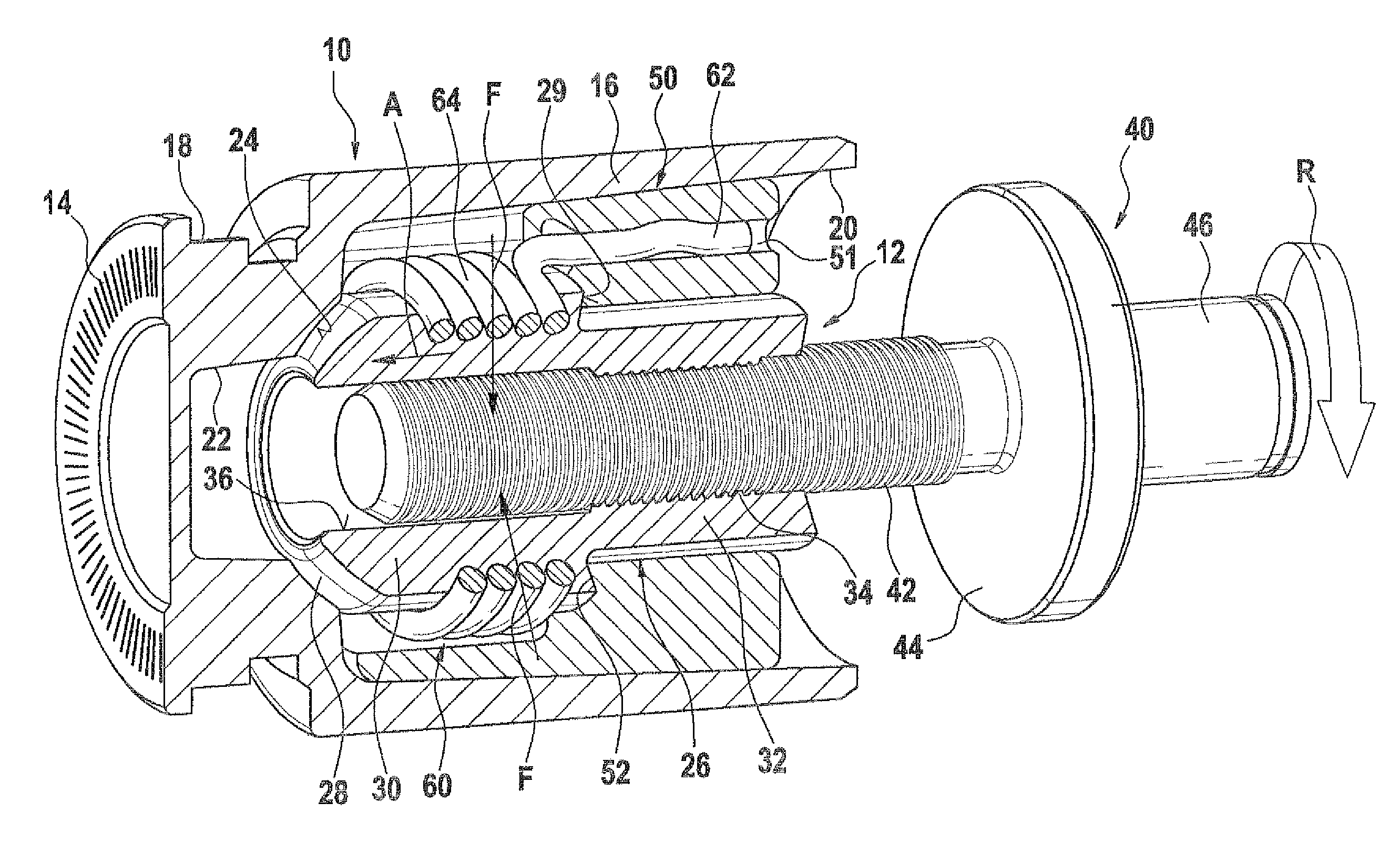
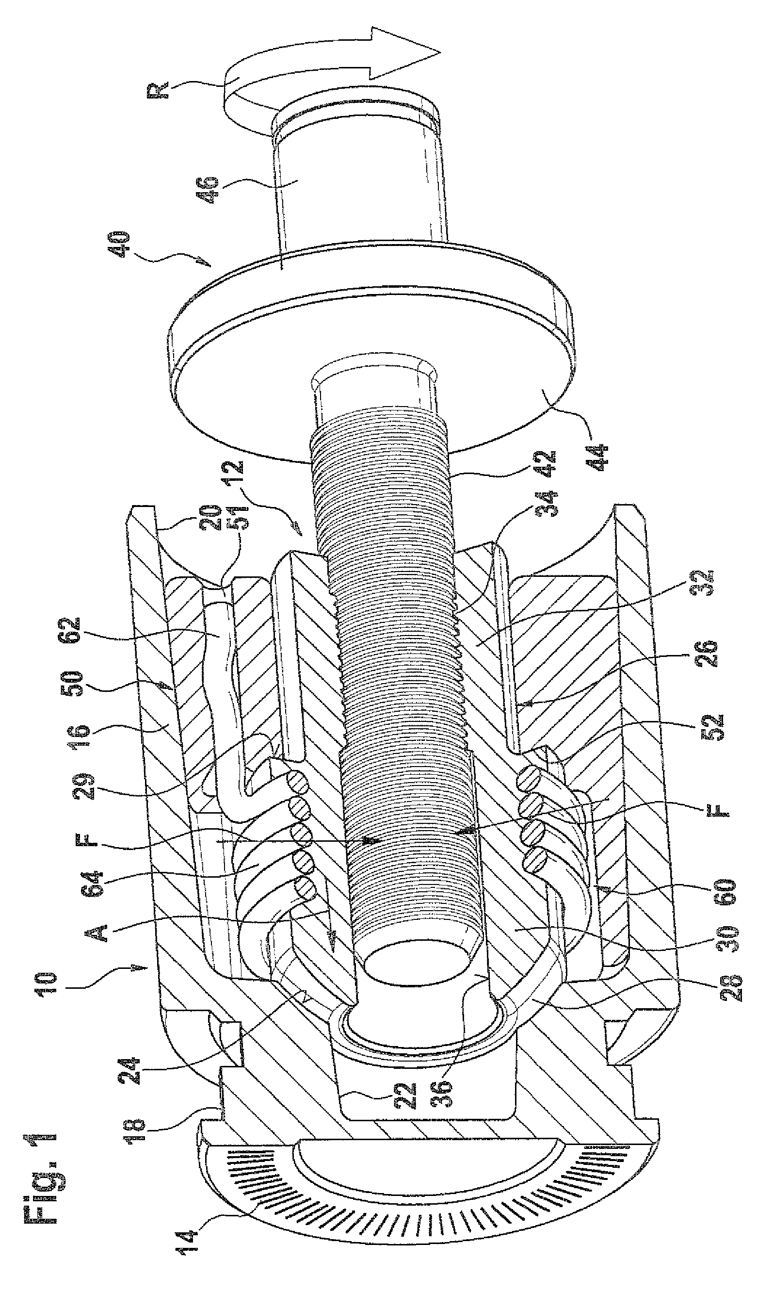
[0018]In FIG. 1, a brake piston 10 is shown, with a locking device 12 built into it. The brake piston 10 is a hollow-cylindrical component, which is closed in pressure-fluid-tight fashion on one of its ends by a lining contact plate 14. The lining contact plate 14 and a piston shaft 16 are embodied in one piece with one another, and on the circumference of the brake piston 10, between the lining contact plate 14 and the piston shaft 16, a recess 18 is provided, which has a single perpendicular graduation from the outside inward. The interior of the brake piston 10 is divided into two portions 20, 22 of different inside diameters. A first portion 20, located at the open end of the brake piston 10, has a larger inside diameter than a second portion 22, which is oriented toward the lining contact plate 14 and is connected to the first portion 20. The transition from the first portion 20 to the second portion 22 is embodied as a conical indentation 24. This conical indentation is locate...


PUM


Abstract

The invention is a electromechanical locking device for a brake piston of a hydraulically actuated wheel brake. The locking device is disposed at least in some portions in the interior of a hollow-cylindrical brake piston. This interior of the brake piston is filled with hydraulic pressure fluid and in the event of brake actuation is subjected to pressure. The invention includes a filler piece and a coupling element, which reduce the pressure-fluid-filled volume of the brake piston, prevent blocking of the locking device in its terminal positions, and make it possible for the two terminal positions of the locking device to be detected and evaluated by an electronic control unit.

Description

CROSS-REFERENCE TO RELATED APPLICATIONS[0001]This application is based on German Patent Application No. 10 2007 053 278.6 filed on Nov. 8, 2007, upon which priority is claimed.BACKGROUND OF THE INVENTION[0002]1. Field of the Invention[0003]The invention is based on an electromechanical locking device for a brake piston of a hydraulically actuated wheel brake.[0004]2. Description of the Prior Art[0005]One such electromechanical locking device is know for instance from German Patent Disclosure DE 10 2005 055 084 A1. The wheel brake disclosed in this reference is hydraulically actuatable. The wheel brake has a hollow-cylindrical brake piston, whose interior is filled with hydraulic pressure fluid. In the event of brake actuation, a hydraulic pressure is built up by the driver of a vehicle. A pressure force causes a displacement of the brake piston relative to a brake cylinder, in which this brake piston is movably guided. The brake piston presses a brake lining against a rotating brake...

Claims


Application Information

Patent Timeline
Patent Type & Authority Patents(United States)
IPC IPC(8): F16D69/00F16D65/18
CPCB60T13/745B60T13/746F16D65/18F16D2121/02F16D2121/14F16D2123/00F16D2125/40F16D2127/06
Inventor TRISTANO, NICOLAGUDEHUS, THORSTENCARUSO, CORRADOONORATO, FRANCESCO
Owner ROBERT BOSCH GMBH
Why Eureka
Try Eureka