Electrically operated seat slide apparatus

a seat slide and electric technology, applied in the direction of machine supports, movable seats, roofs, etc., can solve the problems of increasing the number of parts by the number of parts corresponding to the push-nut, the screw shaft is buckled when receiving compression, and the load receiving member is bent and getting off from the upper rail. , to achieve the effect of reducing the assembly workability of the seat slide apparatus, increasing the number of parts, and reducing the sectional area

Active Publication Date: 2011-11-22
TF METAL CO LTD
View PDF8 Cites 23 Cited by
  • Summary
  • Abstract
  • Description
  • Claims
  • Application Information

AI Technical Summary

Benefits of technology

Japanese Patent Provisional Publication No. 10-203209 may solve the problem encountered in the above seat slide apparatus in Japanese Patent Provisional Publication No. 9-123807. However, in this seat slide apparatus, it is required to provide the damper to the lead screw, together with the damper holding section and the nut member-side plate, thereby increasing the number of parts. Such increase in parts number lowers an assembly workability of the seat slide apparatus. Additionally, although such an electrically operated seat slide apparatus is eagerly required to be small-sized and light-weighted, it is difficult to reduce the sectional area of an upper rail in such a structure that the lead screw is disposed inside the upper rail, for the reason why a member for supporting the nut member is required to be disposed inside the upper rail because the nut member must be supported to the lower rail in the state of being surrounded by a damper in order that the nut member can be movable vertically and laterally so as to absorb the dispersion in dimensions in vertical and lateral directions of the upper and lower rails.
In view of the above, an object of the present invention is to provide an improved electrically operated seat slide apparatus by which an impact load applied to an upper rail is allowed to be directly transmitted to a screw shaft so as to prevent the impact load from being transmitted through a gear box to the screw shaft, and for setting a moving range of the nut.
Another object of the present invention is to provide an improved electrically operated seat slide apparatus having a rail-side stopper which cannot be buckled even upon caulking and is endurable to a bending moment by an axial force, preventing a screw shaft from being buckled.
A further object of the present invention is to provide an improved electrically operated seat slide apparatus which can effectively overcome drawbacks encountered in conventional electrically operated seat slide apparatuses.
According to the present invention, an electrically operated seat slide apparatus comprises a lower rail having a generally U-shape cross-section and fixed to a floor of a vehicle body, and an upper rail having a generally reversed U-shape cross-section and slidably disposed to the lower rail, a seat being connected to the upper rail. A screw shaft is disposed inside the upper rail and extends in a direction of length of the upper rail. A nut is threadedly connected to the screw shaft and connected to the lower rail. A motor is disposed to side of the upper rail. A gear box is located around an axis of the screw shaft and fixed to the upper rail to transmit a rotation of the motor to the screw shaft. Additionally, first and second plates are provided for allowing an impact load applied to the upper rail to be directly transmitted to the screw shaft so as to prevent the impact load from being transmitted through the gear box to the screw shaft, and for setting a moving range of the nut.

Problems solved by technology

However, the electrically operated seat slide apparatus disclosed in Japanese Patent Provisional Publication No. 2001-239861 encounters the following problems: When an impact load is applied to the upper rail, the load receiving member fixed to the upper rail is pushed onto the flange, and therefore the load receiving member fixed to the upper rail is pressed in an axial direction of the upper rail.
As a result, there is the fear that the load receiving member is bent and gets off from the upper rail.
Further, there is a defect that the number of parts increases by that corresponding to the push-nut.
Furthermore, a part of the screw shaft between a gear box and the two flanges undergoes a compression or a tension, and therefore there is the fear that the screw shaft is buckled when receiving the compression.
Additionally, the electrically operated seat slide apparatus disclosed in Japanese Patent Provisional Publication No. 2006-335153 encounters a problem that the rail-side stopper is compressed and buckled to be bent when the stopper plate portions of the rail-side stopper are vertically compressed to be caulked.
Further, the electrically operated seat slide apparatus disclosed in Japanese Patent Provisional Publication No. 9-123807 encounters the following problem: When the nut member strikes against the stopper, the nut member strikes against the stopper which is rotating, so that a torsion is applied to the stopper.
However, in this seat slide apparatus, it is required to provide the damper to the lead screw, together with the damper holding section and the nut member-side plate, thereby increasing the number of parts.
Such increase in parts number lowers an assembly workability of the seat slide apparatus.
Additionally, although such an electrically operated seat slide apparatus is eagerly required to be small-sized and light-weighted, it is difficult to reduce the sectional area of an upper rail in such a structure that the lead screw is disposed inside the upper rail, for the reason why a member for supporting the nut member is required to be disposed inside the upper rail because the nut member must be supported to the lower rail in the state of being surrounded by a damper in order that the nut member can be movable vertically and laterally so as to absorb the dispersion in dimensions in vertical and lateral directions of the upper and lower rails.

Method used


Image

  • Electrically operated seat slide apparatus
  • Electrically operated seat slide apparatus
  • Electrically operated seat slide apparatus

Examples


Embodiment Construction

Referring now to FIGS. 1 to 7, an embodiment of an electrically operated seat slide apparatus according to the present invention is illustrated. The electrically operated seat slide apparatus is mounted on a vehicle body, for example, of an automotive vehicle.

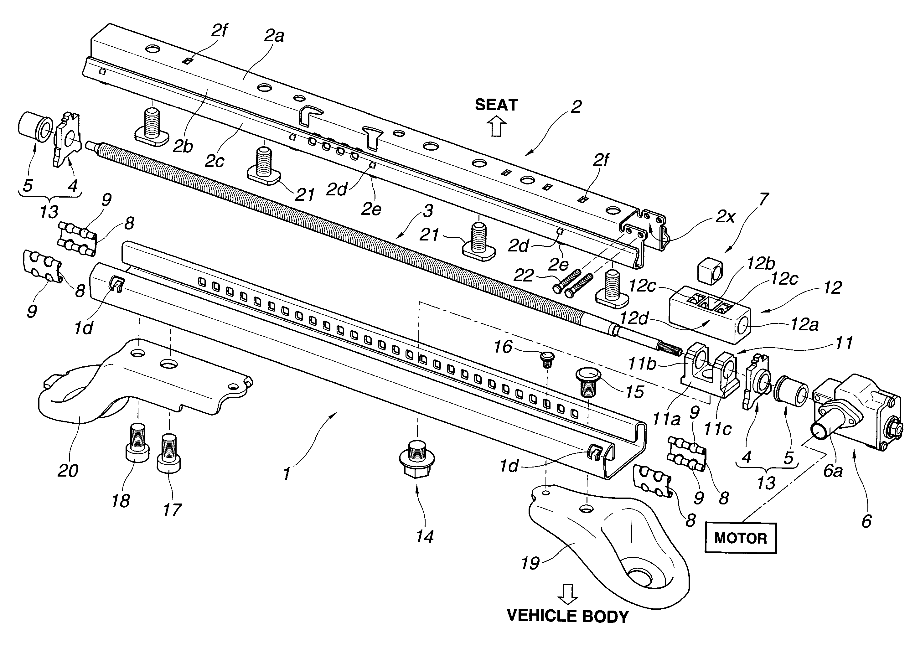
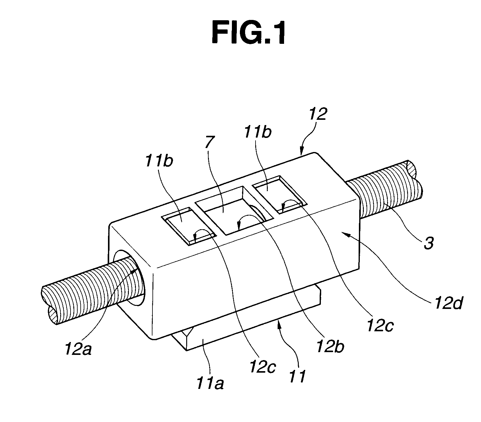
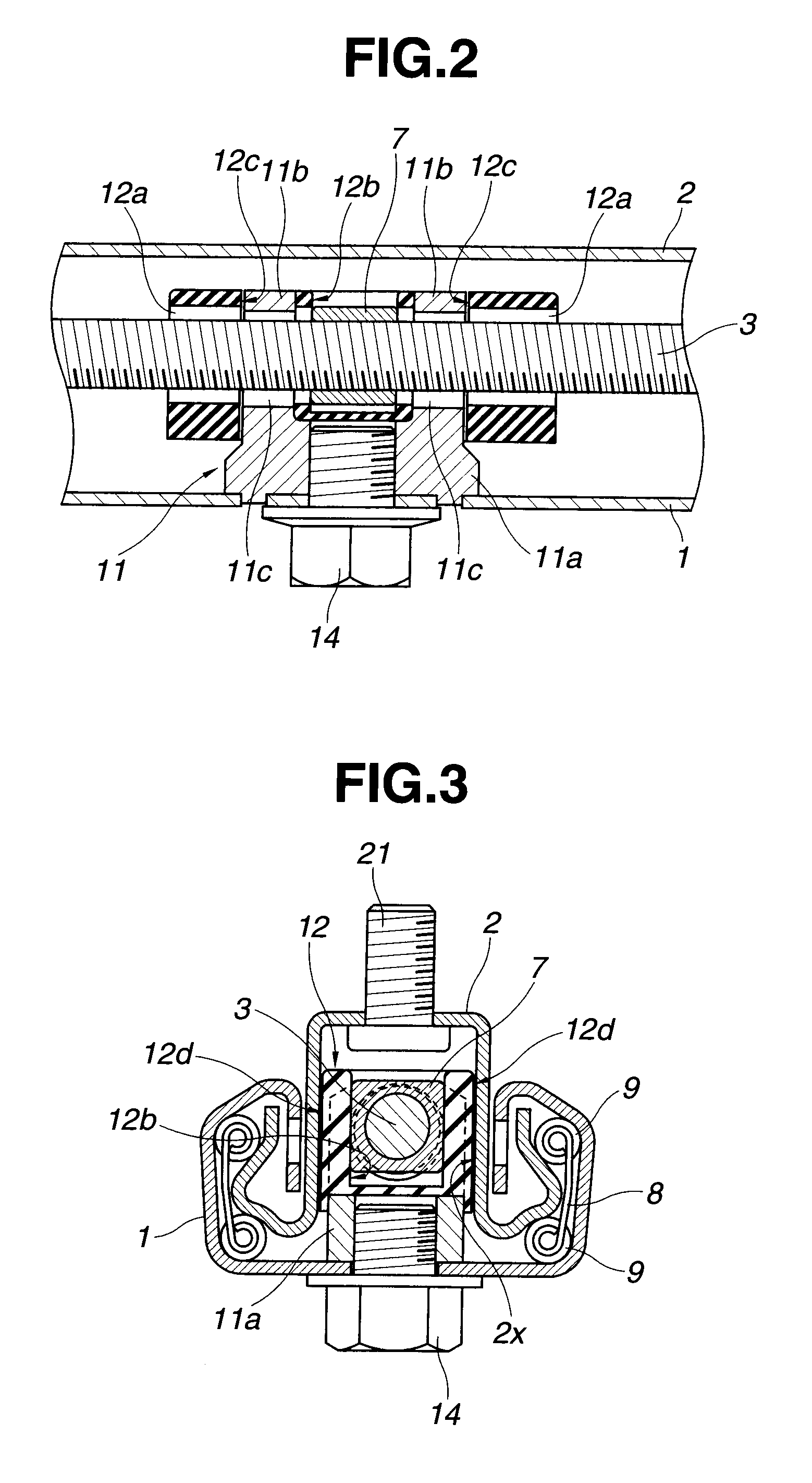
As shown in an exploded perspective view of FIG. 6, the electrically operated seat slide apparatus includes a lower rail 1 fixed to a floor surface of a vehicle body. An upper rail 2 is disposed inside the lower rail 1 so as to be slidable in a lengthwise direction of the upper rail 2. A seat (not shown) is connected to the upper rail 2. A screw shaft 3 is disposed inside the upper rail 2 and extends along the lengthwise direction of the upper rail 2. A nut7 is threadedly connected to the screw shaft 3 and connected to an inside portion of the lower rail 1. An electric motor is disposed to the upper rail 2 so as to rotationally drive the screw shaft 3. A gear box 6 is disposed around or coaxial with the axis of the screw shaft ...


PUM


Abstract

An electrically operated seat slide apparatus includes a lower rail fixed to a floor of a vehicle body, and an upper rail slidably disposed to the lower rail. A seat is connected to the upper rail. A screw shaft is disposed inside the upper rail. A nut is threadedly connected to the screw shaft and connected to the lower rail. A motor is disposed to side of the upper rail. A gear box is fixed to the upper rail to transmit a rotation of the motor to the screw shaft. Additionally, first and second plates are provided for allowing an impact load applied to the upper rail to be directly transmitted to the screw shaft so as to prevent the impact load from being transmitted through the gear box to the screw shaft, and for setting a moving range of the nut.

Description

BACKGROUND OF THE INVENTIONThis invention relates to an electrically operated seat slide apparatus, and more particularly to the seat slide apparatus having a device for directly transmitting an impact applied to an upper rail to a lower rail without transmitting to a gear box.Seat slide apparatuses are classified into manually operated seat slide apparatuses and electrically operated seat slide apparatuses. The manually operated seat slide apparatuses are arranged to manually move a seat in a fore-and-aft direction, whereas the electrically operated seat slide apparatuses are arranged to move a seat in a fore-and-aft direction by a rotational force of an electric motor.One of the electrically operated seat slide apparatuses is disclosed in Japanese Patent Provisional Publication No. 2001-239861. In this electrically operated seat slide apparatus, an upper rail to which a seat is connected is disposed inside a lower rail fixed to a vehicle body. A screw shaft is rotatably disposed i...

Claims


Application Information

Patent Timeline
Patent Type & Authority Patents(United States)
IPC IPC(8): B60N2/02
CPCB60N2/067B60N2/0705B60N2/0715B60N2002/0236B60N2/02253
Inventor KIMATA, TOSHIHIROKANAZAWA, TAKAYA
Owner TF METAL CO LTD
Why Eureka
Try Eureka