Autoclave with underflow dividers

a technology of autoclave and divider, which is applied in the field of superatmospheric reactors and autoclaves, can solve the problems of substantial decrease in metal extraction levels, achieve the effects of promoting abrasion of the autoclave agitator blade and the autoclave lining, reducing short-circuiting levels, and reducing effective operating volum

Inactive Publication Date: 2011-11-22
BARRICK GOLD
View PDF276 Cites 16 Cited by
  • Summary
  • Abstract
  • Description
  • Claims
  • Application Information

AI Technical Summary

Benefits of technology

[0013]To inhibit overflow of the dividers, each of the dividers is set at a level such that it is significantly higher than any wave action that is present due to the highly turbulent surface in the adjacent upstream compartments. The height of the divider is such that free movement of the gas phase along the length of the autoclave is maintained. Although liquid level in the compartments varies from compartment to compartment, the difference in liquid levels between adjacent compartments with underflow type weir dividers is generally less than the liquid level difference between adjacent compartments for overflow weir-type dividers. The lower head drop between compartments for underflow dividers can provide more operating volume (typically at least about 2% more) in the autoclave when compared with an autoclave equipped with standard overflow weirs-type dividers (hereinafter “overflow weirs”).
[0014]To substantially maximize volumetric flow through the autoclave while substantially minimizing short-circuiting and back-mixing, in each of the underflow dividers, the cumulative cross-sectional area of the underflow opening(s) is sized using standard fluid dynamics engineering such that the head drop between compartments is maintained in the range of about 25 to 100 mm. If the openings are made smaller than optimum, the head differential between compartments increases; the advantage of reduced head loss between compartments compared to the overflow configuration is then lost. If the openings are made larger than optimum, the head differential between compartments is further reduced, but this advantage can be more than offset by increased backmixing / short-circuiting created by the larger underflow openings. The cumulative cross-sectional area of the underflow opening(s) in each of the dividers is substantially the same.
[0017]The autoclave can have a number of advantages. For example, the underflow dividers can provide significantly reduced levels of short-circuiting between compartments when compared with overflow weirs. The RTD in compartments separated by underflow dividers is generally closer to ideal plug flow conditions than in compartments separated by overflow weirs. Under identical agitation and aeration conditions, higher mass transfer coefficients can be realized in compartments separated by underflow dividers when compared to compartments separated by overflow weirs. Underflow dividers can inhibit solids build up in compartments. Overflow weir dividers can inhibit the flow of coarser particles through the autoclave. Coarse particles may comprise tramp oversize naturally present in the autoclave feed, dislodged scale build up, or aggregates of feed particles formed in the autoclave. The underflow weir configuration promotes the movement of such coarse particles down the axis of the autoclave to be removed in the autoclave discharge. Non-removal of coarse particles may reduce effective operating volume and may promote abrasion of the autoclave agitator blades and the autoclave lining. When compared to standard overflow weir-type dividers, underflow dividers are thus easier to design and construct. Typically, overflow weir dividers must be designed to support the full head of liquid slurry in the upstream compartment. With underflow weir divers, this head differential between adjacent compartments cannot develop. Thus, underflow weir dividers require less wall thickness and fewer structural members. With underflow weir dividers, when the autoclave is taken out of service for maintenance, slurry can be more readily removed from the autoclave without lengthy and labor-intensive liquid and solid removal procedures for each individual compartment.

Problems solved by technology

Short circuiting, or moving to the next compartment with an unacceptably short residence time in a compartment, can cause a substantial decrease in metal extraction levels.

Method used


Image

  • Autoclave with underflow dividers
  • Autoclave with underflow dividers
  • Autoclave with underflow dividers

Examples


Embodiment Construction

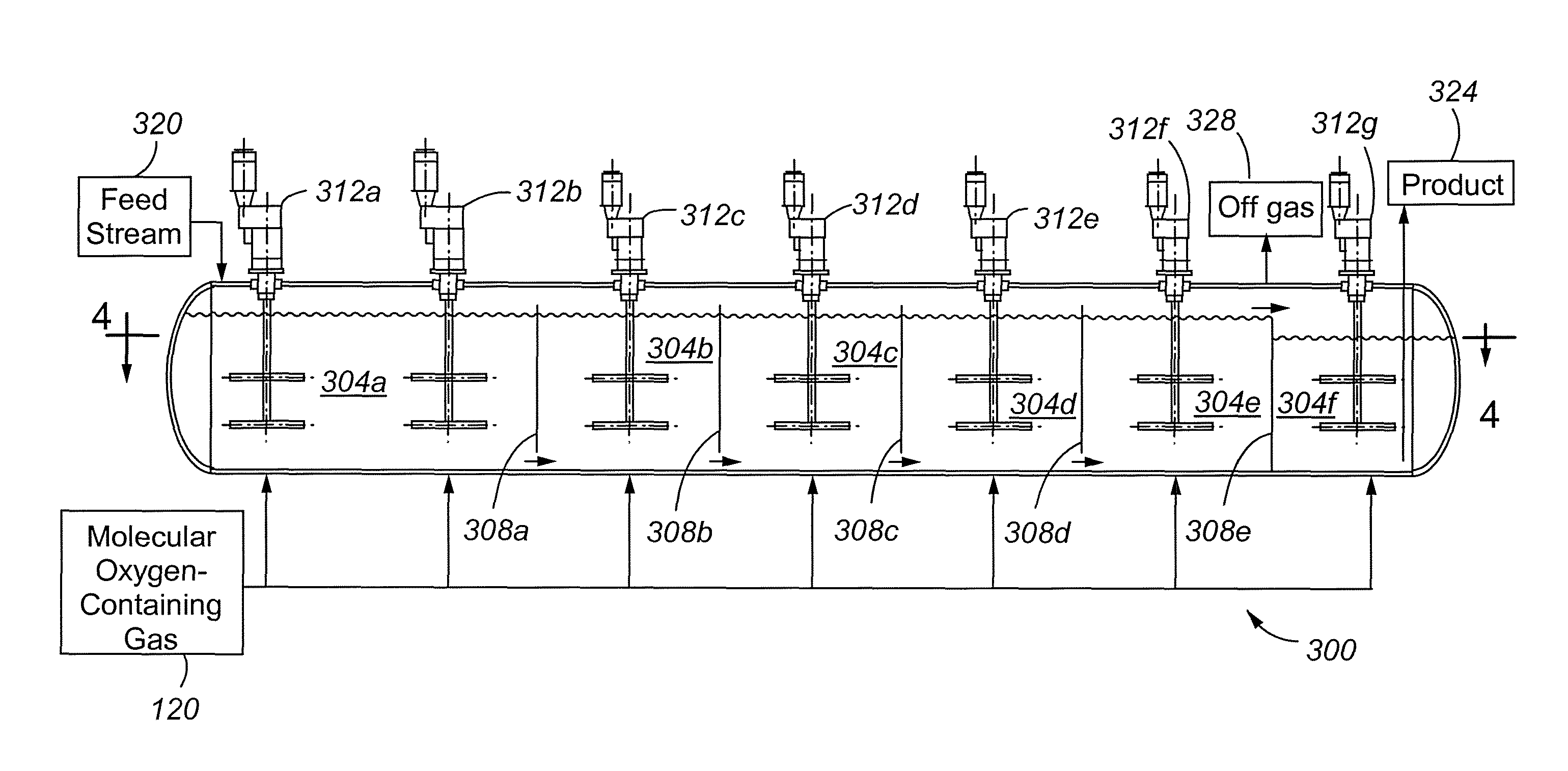
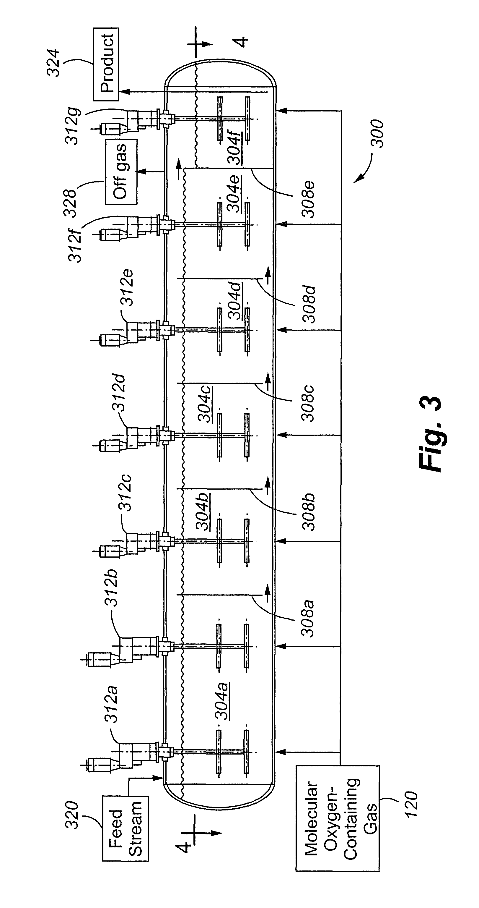
[0038]An embodiment of the present invention will be discussed with reference to FIGS. 3-5. The autoclave 300 of a first embodiment of the present invention includes a plurality of compartments 304a-f separated by dividers 308a-e. Although the autoclave is shown as having only five compartments, it is to be understood that the autoclave can have more or fewer than five compartments, depending on the application. As can be seen by the arrows in FIG. 3, the dividers 308a-d are underflow dividers while the last divider 308f may be an overflow weir (such as the weir of FIG. 2). The use of an overflow divider between the last compartment and the next-to-last compartment can help provide a wider variation and greater sensitivity in liquid level in the last compartment, which will facilitate dynamic level control driving periods of fluctuating flow of the feed stream. The provision of an overflow divider in the last compartment is deemed less necessary as the member of autoclave compartmen...


PUM

PropertyMeasurementUnit
areaaaaaaaaaaa
partial pressureaaaaaaaaaa
operating temperatureaaaaaaaaaa

Abstract

The present invention is directed to a multi-compartment autoclave using inter-compartment dividers having one or more underflow openings for passing a feed stream between compartments.

Description

CROSS REFERENCE TO RELATED APPLICATION[0001]The present application claims the benefits of U.S. Provisional Application Ser. No. 60 / 783,295, filed Mar. 17, 2006, entitled “Autoclave with Underflow Dividers”, which is incorporated herein by this reference.FIELD OF THE INVENTION[0002]The invention relates generally to reactors and particularly to superatmospheric reactors, especially autoclaves.BACKGROUND OF THE INVENTION[0003]Autoclave reactors have a wide range of applications in chemical processes. A typical autoclave has one or more compartments and operates at elevated pressures and temperatures. Most autoclaves are heated by steam injection, autogenous heat generated by reactions within the autoclave, or by a combination of both.[0004]In most applications, autoclaves are stirred, multi-compartment reactors. An example of a multi-compartment, cylindrical autoclave is shown in FIGS. 1 and 2. The reactor 100 has a plurality of compartments 104a-f, each compartment 104 having at lea...

Claims


Application Information

Patent Timeline
Patent Type & Authority Patents(United States)
IPC IPC(8): B01F7/20B01F13/06B01J3/04B01F27/906
CPCB01F7/00975B01F7/18B01F13/1013B01F13/1022B01F15/00863B01J3/042B01J19/006B01J2219/00768B01J2219/182B01F27/2322B01F33/813B01F33/81B01F27/90B01F35/52B01J3/04
Inventor JI, JINXINGKING, JAMES A.
Owner BARRICK GOLD
Why Eureka
Try Eureka