Velocity-changing apparatus for web

a technology of velocity-changing apparatus and web, which is applied in the field of velocity-changing apparatus for web, can solve the problems slowing down the production line, and requiring more processing time for processing of web by ultrasonic welding, and achieves the effect of reducing production efficiency and more processing tim

Inactive Publication Date: 2011-11-22
ZUIKO CORP
View PDF32 Cites 38 Cited by
  • Summary
  • Abstract
  • Description
  • Claims
  • Application Information

AI Technical Summary

Benefits of technology

[0007]Generally, processing of the web by ultrasonic welding requires more time for processing than that by heat sealing. Therefore, introducing the ultrasonic welding in place of the heat sealing into the existing production line might cause slowdown of the production line as a whole, thereby decreasing the production efficiency.
[0008]An object of the present invention is to provide a new velocity-changing apparatus for a web that can be incorporated into the production line without decreasing the speed of the production line as a whole.
[0010]In this velocity-changing apparatus, the rotational velocity of the drum is changed periodically while the continuous web is being transported by means of the rotation of the drum. Thus, the transport velocity of the continuous web, which is transported by the drum, is changed periodically. Furthermore, the movable member moves periodically so that the feed velocity of the continuous web decreases when the transport velocity of the continuous web on the drum decreases and that the feed velocity of the continuous web increases when the transport velocity of the continuous web on the drum increases. Thus, the continuous web on the drum or on the upstream side of the drum can be prevented from substantially slacking or shrinking.
[0013]In this aspect, the continuous web on the drum can be processed when the circumferential velocity of the drum slows down, i.e., the transport velocity of the continuous web slows down, which allows for more time for processing. On the other hand, the transport velocity of the continuous web can be accelerated by accelerating the circumferential velocity of the drum when the processing is not performed, which makes the average transport velocity of the continuous web in conformity with the speed of the production line as a whole.
[0015]According to another preferred aspect of the present invention, the cutter cut the continuous web when the transport velocity at which the drum transports the continuous web is lower than the average circumferential velocity of the drum. In this aspect, the accuracy of cutting can be improved.
[0017]In this aspect, after the cutter cuts the continuous web, the cut-off web produced by cutting the continuous web can be transported (moved) at a velocity which is higher than the circumferential velocity of the drum at the time of the cutting. Furthermore, since the receiving device transports (moves) the cut-off web at such a higher velocity, the tip end of the continuous web can get away from the rear end of the cut-off web. Thus, even when the transport velocity of the continuous web is accelerated after this spacing, the front end of the continuous web can be prevented from interfering with the rear end of the cut-off web.

Problems solved by technology

Generally, processing of the web by ultrasonic welding requires more time for processing than that by heat sealing.
Therefore, introducing the ultrasonic welding in place of the heat sealing into the existing production line might cause slowdown of the production line as a whole, thereby decreasing the production efficiency.

Method used


Image

  • Velocity-changing apparatus for web
  • Velocity-changing apparatus for web
  • Velocity-changing apparatus for web

Examples


first embodiment

[0037]Embodiments of the present invention will now be described with reference to the drawings.

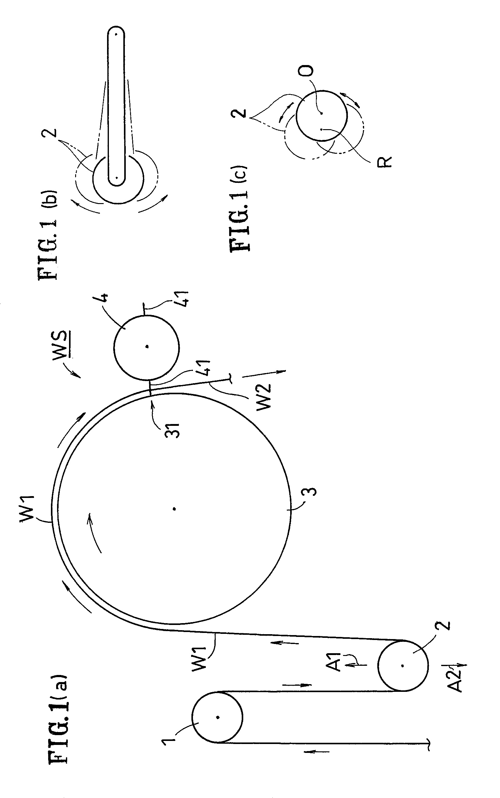
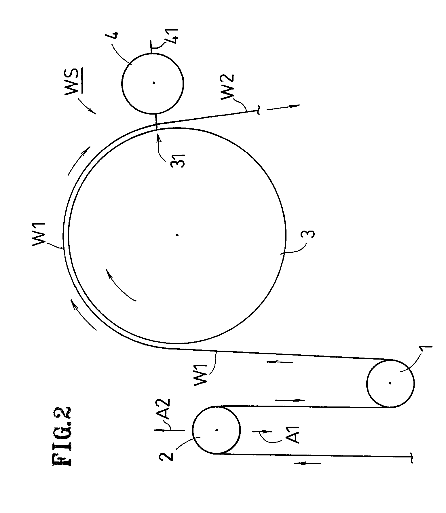
[0038]FIG. 1 shows the first embodiment, which includes a velocity-changing apparatus WS for web.

[0039]According to this embodiment, the velocity-changing apparatus WS includes a movable roller 2 (an example of movable member), a work drum 3 and a cutter roller 4. A fixed roller 1 may be located upstream of the movable roller 2. A continuous web W1 is fed successively to the work drum 3 from the movable roller 2, which is located upstream of the work drum 3. On the outer circumferential surface of the cutter roller 4, two blades 41 are provided. One or more blade rests (beds) for receiving the blades 41 may be provided on the work drum 3.

[0040]The work drum 3 can rotate while changing periodically its circumferential velocity V(θ) (peripheral velocity). Thus, in a case where a processing device is provided on the work drum 3, the work drum 3 enables the continuous web W1 to move at a velo...

second embodiment

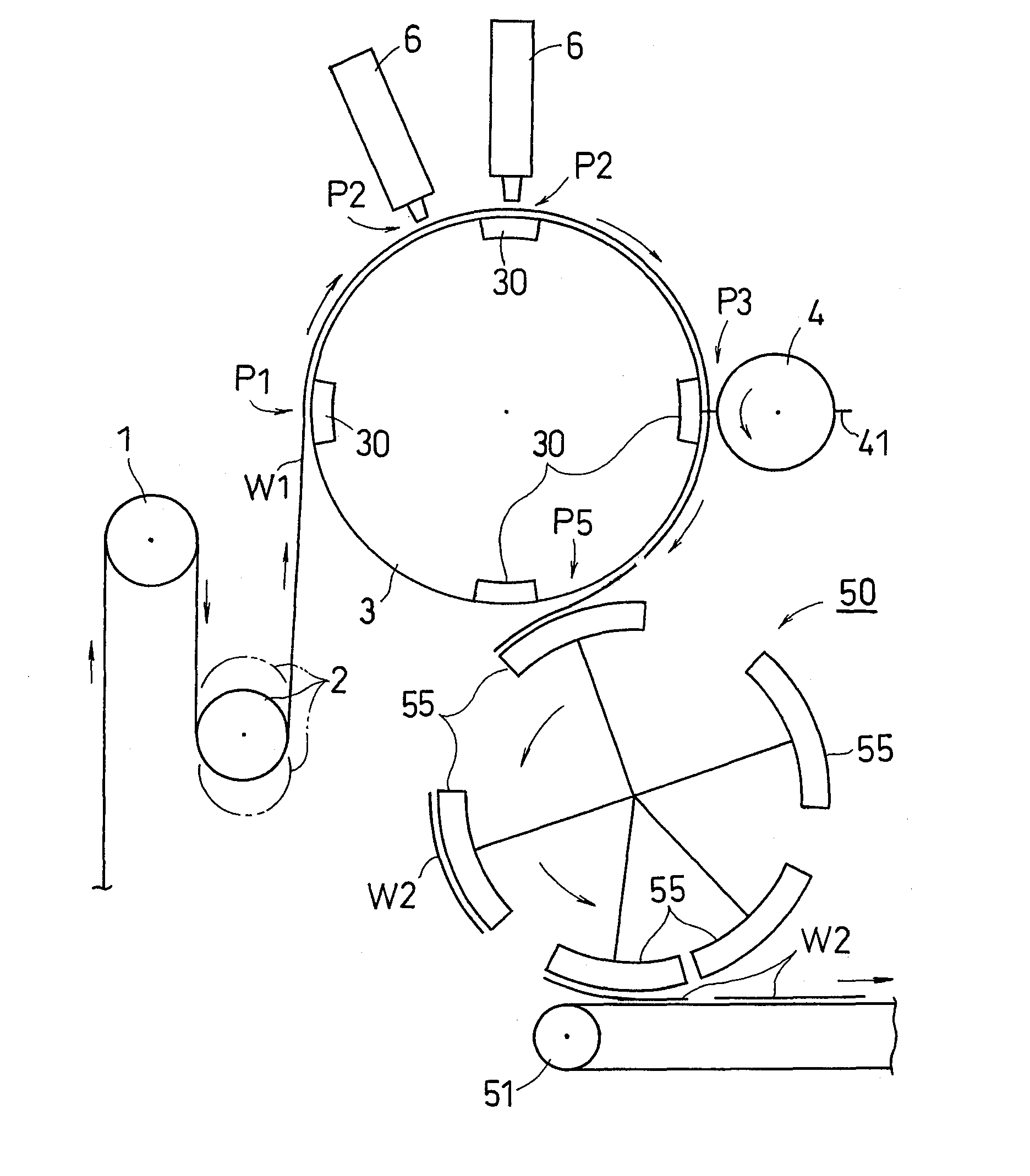
[0056]The velocity-changing apparatus of the present invention may include a processing device. The processing device is capable of carrying out steps of cutting, forming holes, sealing, attaching or applying something, or the like. For example, in a case of welding or sealing the continuous web W1, ultrasonic welding means or heat sealing means may be employed thereto. Hereinafter, the second embodiment, in which ultrasonic welding means is used, will be described with reference to FIGS. 3(a), 3(b).

[0057]At least one main body of the processing device 6 is located around the work drum 3. As shown in FIGS. 3(a), 3(b), the work drum 3 may include a plurality of anvils (receiving beds) 30. In addition, the work drum 3 may hold the continuous web W1 by suction or by mechanical means at the anvils 30 and / or a portion other than the anvils 30.

[0058]As shown in FIG. 3(a), the continuous web W1 is received by the work drum 3 at a receiving position P1 of the work drum 3 and is processed at...

third embodiment

[0068]FIG. 4 shows the third embodiment.

[0069]In this embodiment, as shown in FIG. 4, a adjustment drum having a plurality of pads 55 is employed as the receiving device 50, in which drum the interval between the pads is adjusted by rotating the pads 55 while changing their circumferential velocity. For example, the circumferential velocity of the pad 55 may reach its maximum at the hand-over position P5 and then be decreased to a velocity commensurate with the velocity of the conveyor 51 when the cut-off web W2 is transferred to the conveyor 51. A structure as disclosed in Japanese Laid-Open Patent Publication No. 2002-345889 may be employed for the adjustment drum.


PUM

PropertyMeasurementUnit
timeaaaaaaaaaa
processingaaaaaaaaaa
speedaaaaaaaaaa

Abstract

A velocity-changing apparatus of the present invention includes: a drum 3 for transporting the continuous web W1 at a transport velocity which is generally equal to a circumferential velocity V(θ) of the drum 3 while changing the circumferential velocity V(θ) periodically at least once per one rotation of the drum 3; a movable member 2 disposed upstream of the drum 3 for feeding the continuous web W1 to the drum 3,; and a cutter 4 for cutting, on the drum 3, the continuous web W1 being transported at the transport velocity which is generally equal to the circumferential velocity V(θ) of the drum 3. The movable member 2 moves according to the change of the circumferential velocity V(θ) of the drum 3 so that a feed velocity at which the continuous web W1 is fed to the drum 3 is generally equal to the transport velocity of the continuous web W1 being transported by the drum 3.

Description

[0001]This application is a continuation application of U.S. Non-Provisional application Ser. No. 10 / 598,265 filed on Aug. 23, 2006 now abandoned which is a 371 of International Application No. PCT / JP2005 / 003355 filed in Japan on Mar. 1, 2005, the entire contents of which are hereby incorporated by reference.TECHNICAL FIELD[0002]The present invention relates to a velocity-changing apparatus for a web, wherein predetermined processing can be added onto the web while the web is being transported.BACKGROUND ART[0003]When a processing such as bonding is added onto the web which is being carried, a certain amount of time for the processing is required. The time for processing can be gained by decreasing the speed of the whole production line, but it might lead to decreased production efficiency. Velocity-changing apparatuses and apparatuses for producing absorbent articles, in which apparatuses the velocity of the web can be slowed down during the processing of the web with the speed of ...

Claims


Application Information

Patent Timeline
Patent Type & Authority Patents(United States)
IPC IPC(8): B32B37/00B32B38/04B32B38/00B26D1/40B65H20/04B65H20/24B65H23/04B65H23/188B65H35/08
CPCB65H20/04B65H20/24B65H23/048B65H23/188B65H35/08B26D1/405Y10T156/12Y10T156/1052Y10T156/1712Y10T156/1062Y10T156/1056Y10T156/1057B65H2301/122
Inventor NAKAKADO, MASAKIMIYOSHI, AKIHIRO
Owner ZUIKO CORP
Why Eureka
Try Eureka