Underground stormwater management system and method

a management system and underground technology, applied in the field of stormwater treatment, can solve the problems of high-head filter use, difficult to locate, high cost of building and maintaining two stormwater systems, etc., and achieve the effect of reducing cost and more efficient use of si

Inactive Publication Date: 2011-11-22
LANE ENTERPRISES
View PDF21 Cites 7 Cited by
  • Summary
  • Abstract
  • Description
  • Claims
  • Application Information

AI Technical Summary

Benefits of technology

[0017]The storage chamber in some embodiments includes a perforated storage section or portion that enables runoff in the perforated storage portion to discharge directly into surrounding permeable media. This enables the surrounding media to increase the effective storage capacity of the system.
[0019]The underground stormwater management system of the present invention is capable of both treating first flush and storing and accumulating a large volume of runoff using the same storage chamber. There is no need for separate stormwater treatment and stormwater management systems, thereby reducing cost and making more efficient use of the site in managing stormwater runoff.

Problems solved by technology

The discharge is normally not filtered, but if filtering is desired an expensive high-head filter must be used because of the high volume and flow of runoff being filtered.
Building and maintaining two stormwater systems is expensive and can be difficult to locate on some sites.

Method used


Image

  • Underground stormwater management system and method
  • Underground stormwater management system and method
  • Underground stormwater management system and method

Examples


second embodiment

[0065]FIG. 12 illustrates a second embodiment USMS 210 that includes a receiving tank 224 identical to the receiving tank 24 and a storage chamber 226 similar to storage chamber 226. Only the differences between storage chamber 26 and storage chamber 226 will be discussed, it being understood the other elements remain the same as previously described.

[0066]USMS 210 includes a perforated storage tank 266c similar to perforated storage tank 66c. The open ends of the tank 266c are partially closed by weirs formed by respective weir plates 212. See FIGS. 13 and 14. The illustrated weir plates 212 each extends upwardly from the bottom of the storage tank to an upper edge located one foot, nine inches above the bottom of the storage tank.

[0067]USMS 210 also replaces the single discharge 32 with multiple discharge pipes 232a, 232b, and 232c spaced along the length of the front storage tank 268. See FIGS. 12 and 15. The multiple discharge pipes 232 communicate with the main discharge pipe 2...

third embodiment

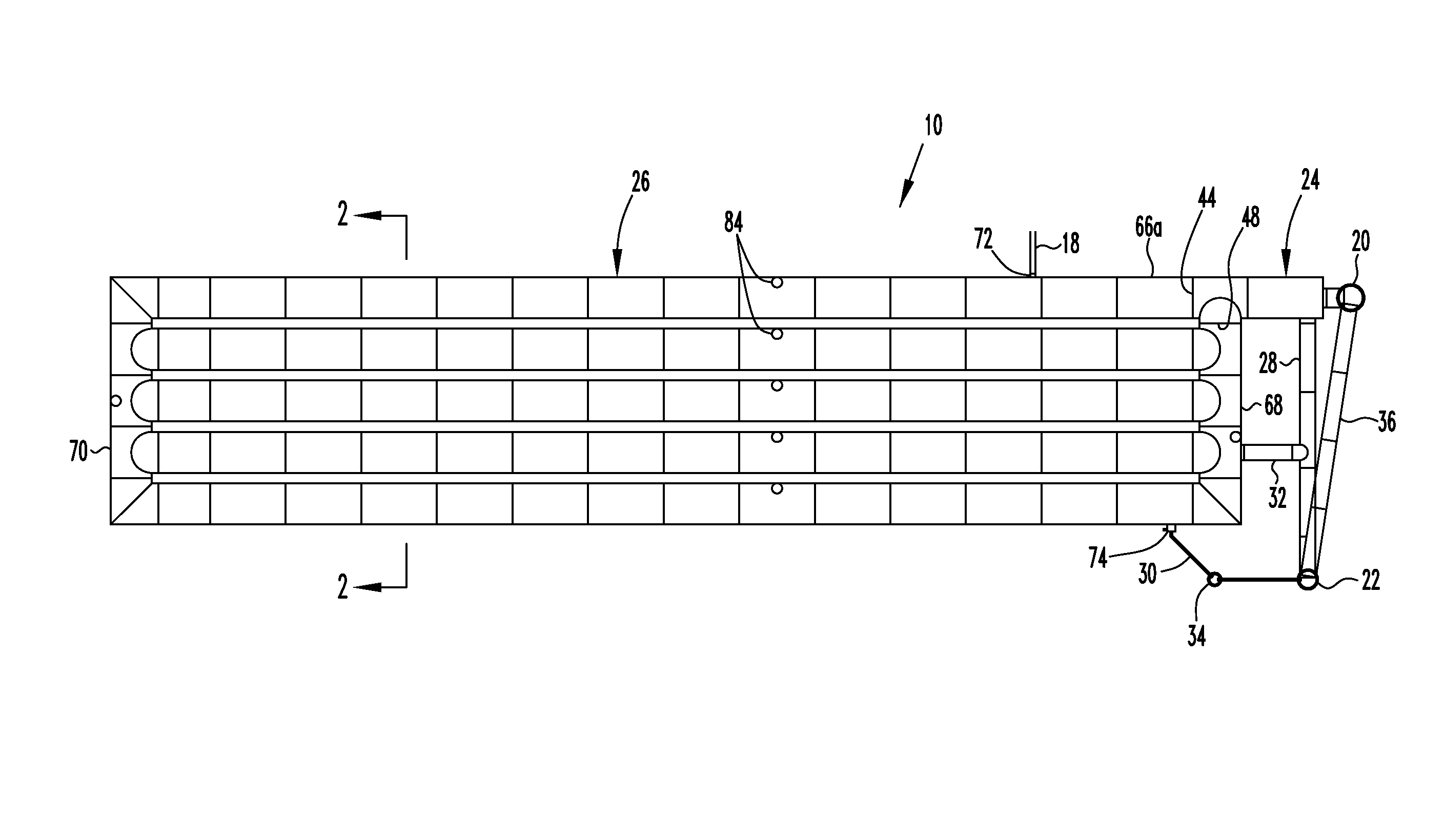
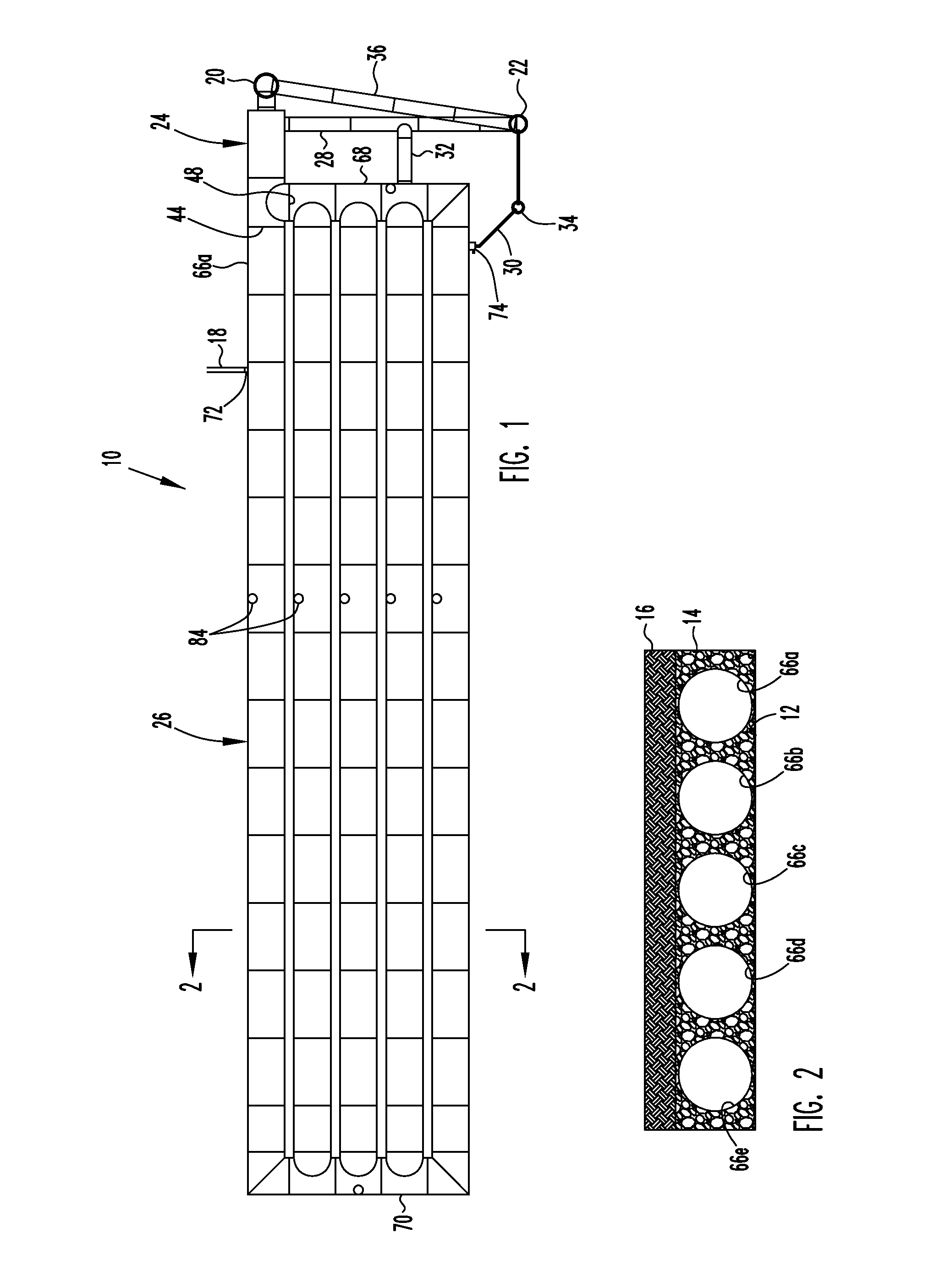
[0072]FIG. 16 illustrates schematically a portion of a third embodiment storage chamber 326 similar to storage chamber 26. The storage chamber 326 includes a perforated storage tank 366c located to one side of a solid storage portion 312. The solid storage portion 312 defines a flow path extending between the inlets and discharges of the storage chamber 326 as previously described.

[0073]Bulkheads 314, 316 close the ends of the storage tank 366c. A flow conduit 318 fluidly connects one end of the storage tank 366c to the solid storage portion 312. The relative elevation 320 of the flow conduit 318 establishes the water level at which water flows from the solid storage portion into the perforated storage portion, and performs essentially the same function as the weirs 212 to prevent flow into the perforated storage portion and then to the surrounding media until the water level in the solid storage portion reaches a predetermined elevation.

[0074]In yet other embodiments the perforated...


PUM

PropertyMeasurementUnit
volumeaaaaaaaaaa
elevationaaaaaaaaaa
cross-sectional areaaaaaaaaaaa

Abstract

An underground stormwater management system includes a receiving tank connected to a source of non-first flush runoff and a storage chamber that accumulates stormwater runoff for discharge to a storm drain. The storage chamber includes a first inlet connected to a source of first flush runoff, a second inlet connected to receive overflow from the receiving tank, a first discharge and a second discharge above the first discharge. First flush is discharged from the first discharge and is filtered before reaching the storm drain. The receiving tank assists in delaying the receipt of non-first flush runoff into the storage chamber during a major rain event. During major rain events runoff is also discharged from the storage chamber directly to the surrounding media.

Description

[0001]This application claims priority to my U.S. Provisional Patent Application No. 61 / 085,062 filed Jul. 31, 2008.FIELD OF THE INVENTION[0002]The invention relates generally to stormwater treatment, and particularly to an underground stormwater management system and method for receiving and discharging stormwater runoff to a storm drain.BACKGROUND OF THE INVENTION[0003]Stormwater runoff includes the initial runoff or “first flush” that contains sediments, oil, and other pollutants flushed from surface areas, and other runoff that can be considered essentially pollution-free. The pollution-free runoff includes the later runoff from the surface areas that generated the first flush, and runoff from areas without surface pollutants. In major storm events the volume of non-first flush is substantially greater than the volume of first flush.[0004]Stormwater treatment systems have been developed to remove pollutants from the first flush. Conventional first flush treatment systems include...

Claims


Application Information

Patent Timeline
Patent Type & Authority Patents(United States)
IPC IPC(8): E03F5/14
CPCE03F1/005E03F2201/10
Inventor LOBELLO, EDWARD H.
Owner LANE ENTERPRISES
Why Eureka
Try Eureka