Eureka AIR delivers breakthrough ideas for toughest innovation challenges, trusted by R&D personnel around the world.

Apparatus and methods for use in concentration of gas and particle-laden gas flows

a technology of gas flow and apparatus, which is applied in the direction of chemical/physical process, biological material analysis, liquid gas reaction process, etc., can solve the problems of introducing bias into determination, not addressing maintaining and preserving the distinction in the trace organic species phase (vapor or condensed on particles, relative gas to particle velocity, etc., to achieve the effect of minimizing adsorption or desorption

Inactive Publication Date: 2011-11-22
ENVIRONMENTAL PROTECTION AGENCY US
View PDF7 Cites 0 Cited by
  • Summary
  • Abstract
  • Description
  • Claims
  • Application Information

AI Technical Summary

Benefits of technology

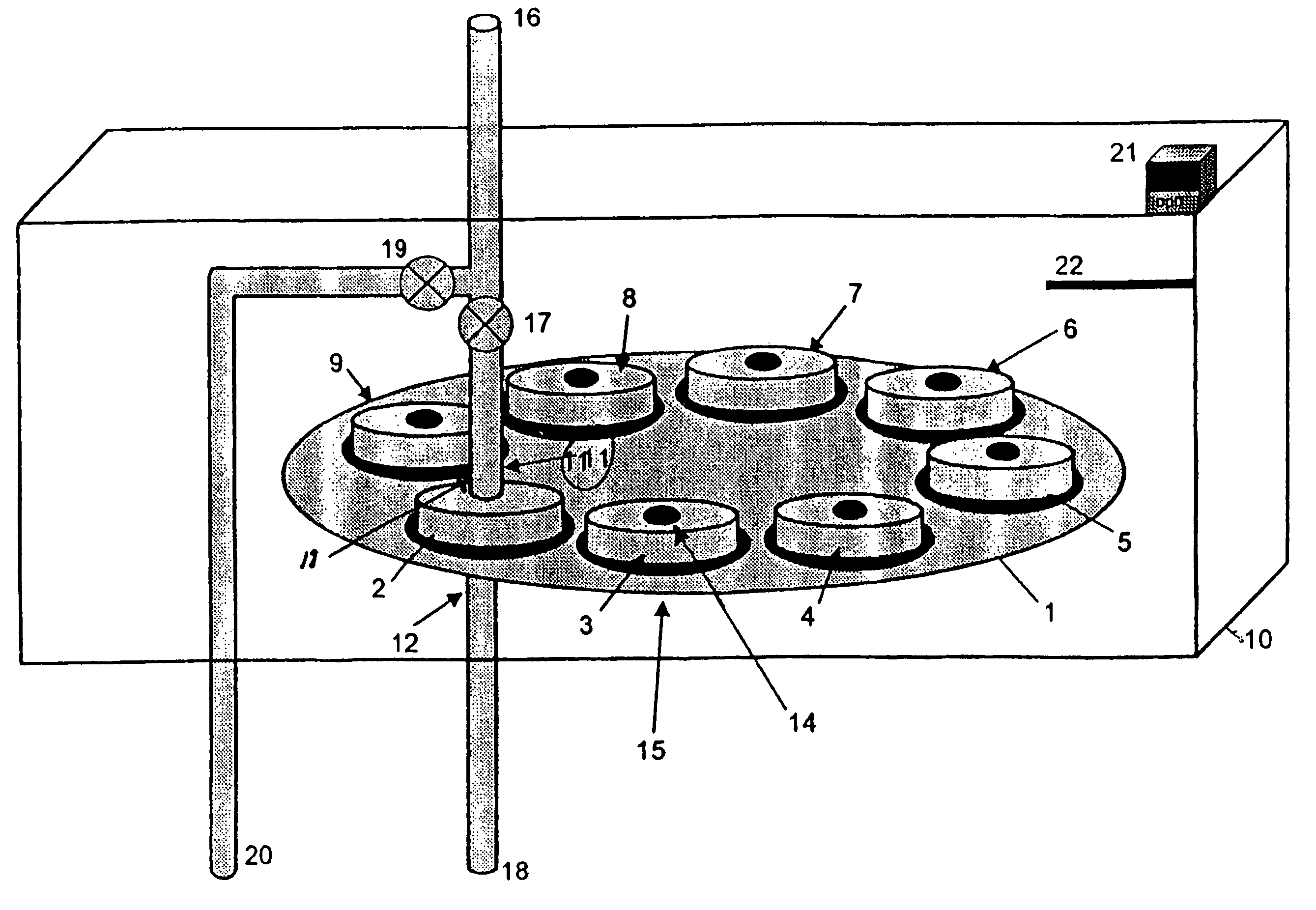
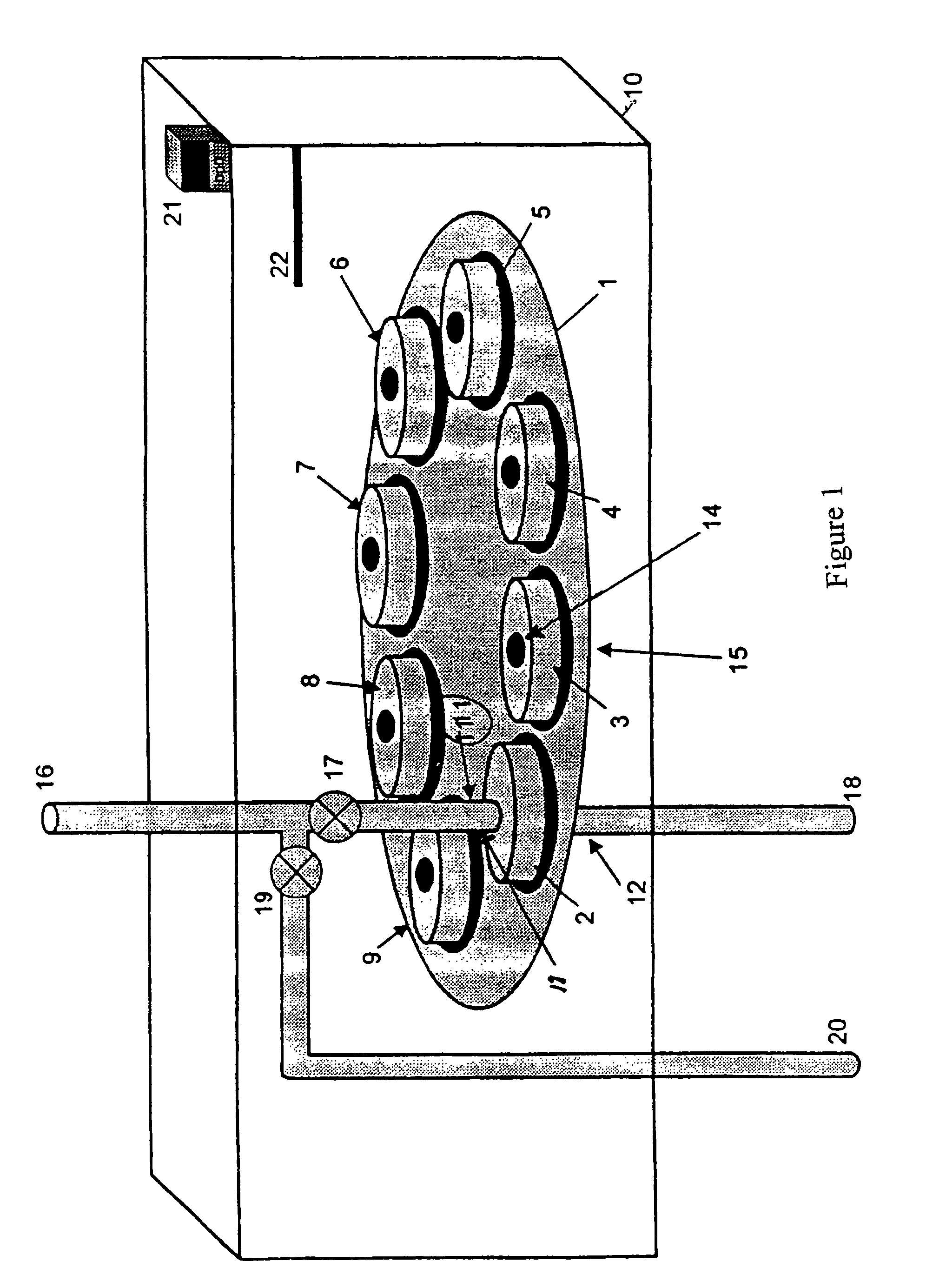
[0008]This invention provides a gas / particle sampling method for separation and concentration of volatile and / or semi-volatile gas / vapor analytes that are present in dilute concentrations in a gas stream phase or as a condensed phase on particles within the stream. The target analytes can be delivered in gaseous form to a suitably fast analyzer and their concentration determined in a time period whose duration is dependent on the analyte, its concentration and the phase separation properties. A key feature of the method is its ability to preserve the analyte's gas / particle partitioning by minimizing adsorption or desorption of analytes onto the particle-laden filtering surface. One aspect of the invention is the use of a filter having continually refreshed surfaces. The filter exemplified has rotating filters which can be repeatedly refreshed. However, a filtering tape can also provide means of providing fresh surfaces to collect particles.
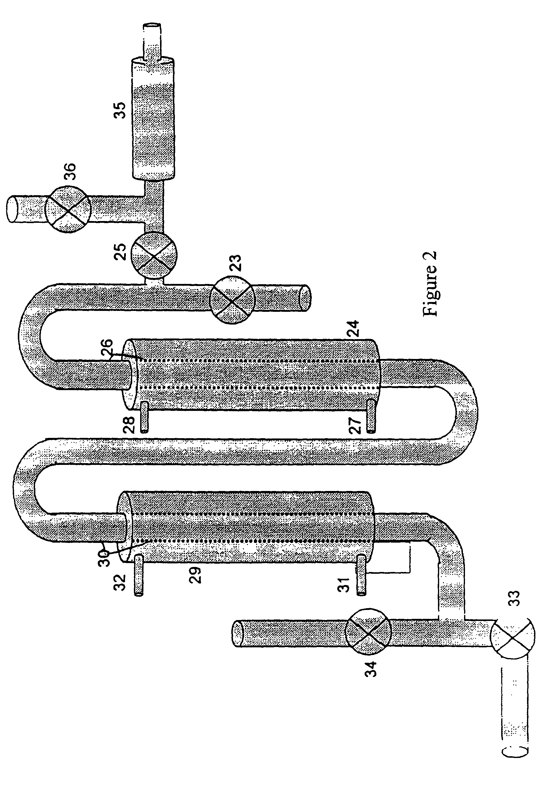
[0009]The device for use in the practice of the invention comprises at least one sorbent bed through which is passed a gas supposed to contain a target analyte. The bed is essentially concentric with a passage way containing thermal fluid such as a tube which may either surround the sorbent bed (see FIG. 2) or the sorbent bed may surround the passage way (FIG. 5). The thermal fluid passage way is accessed through an entrance port and an exit port which allows a heat transfer thermal fluid to flow into and out of the passage way. After passage through one or more sorbent beds, the gas may be passed through a cryotrap to significantly shorten the time duration in which the target analytes are released from the system to the analyzer. (Concentric, in this specification, represents passages which would be orientated around a common center point on a line passed through a cross section of the concentrator.)
[0010]The methods of the invention provide for concentrating target gas analytes into a small volume gas sample while minimizing blow-off and blow-on of the target gas analytes through a filtration system which, separate or in combination, provide a particle-free, concentrated gas stream containing the sample of gas-phase target analyte which can then be sent to an appropriate end processor, such as an analytical gas monitor. Particles are removed by a filtration apparatus which has multiple filters, allowing for incremental refreshment of the filter surface to minimize the exposure time of the captured particles to the flowing gas, thereby minimizing blow-off and blow-on. Volatile and semi-volatile target gases are removed from a flowing gas stream by diffusion and / or adsorption to a cold sorbent resin bed.

Problems solved by technology

These sampling artifacts introduce bias into determinations of phase partitioning of volatile and semi-volatile compounds.
These methods teach gas phase target concentration, but do not address maintaining and preserving the distinction in the trace organic species phase (vapor or condensed on particles) as exists at the point of sampling.
This method can provide a gas versus particle phase distribution, but can suffer considerable bias from the blow-off and blow-on phenomena discussed above, and, hence, is not purported as a method for discerning analyte phase partitioning.
That method of segregation increases the relative gas to particle velocity, thus exacerbating concerns over particle blow-off and blow-on.
None of the references teach a method for limiting gas flow through previously filtered particles, thereby minimizing blow-off and blow-on complications.

Method used


Image

  • Apparatus and methods for use in concentration of gas and particle-laden gas flows
  • Apparatus and methods for use in concentration of gas and particle-laden gas flows
  • Apparatus and methods for use in concentration of gas and particle-laden gas flows

Examples


Embodiment Construction

[0020]It is a purpose of this invention to provide an apparatus and methods for operation of said apparatus for sampling gases containing trace organic species, both in the vapor phase and as condensed on particles, and to concentrate the target trace organic species. Means for surpassing analytical detection method limits of a gas analyzer prior to passing the collected sample containing the target analyte to the analyzer are also taught herein. It is also the purpose of the invention to provide means for distinguishing between the trace organic species that are in the vapor phase from those which were bound to the particulate phase in such a manner that there is no alteration that would prevent such distinction. Using methods of the invention it is possible to make such a distinguishing analysis without passing the particles, to which the target species may be bound, to the analyzer. This is important, since many analyzers can not tolerate the presence of such particles.

[0021]This...


PUM

PropertyMeasurementUnit
flow rateaaaaaaaaaa
temperatureaaaaaaaaaa

Abstract

For analysis of small quatities of target analytes in an environment, the gas flow can be delivered to a suitably fast analyzer and their concentration determined in a time period whose duration is dependent on the analyte, its concentration and the phase separation properties. A device having a sorbent bed that is essentially concentric with a passage way containing thermal fluid is used to concentrate the target analyte.

Description

[0001]This application takes priority from Provisional Patent Application 60 / 681,146 filed May 16, 2005.FIELD AND BACKGROUND OF THE INVENTION[0002]The present invention relates to an apparatus for sampling particle-laden gas flows and concentrating trace organic species within that flow for subsequent analysis by gas phase detectors.[0003]Environmental sampling for target chemical species often requires knowledge of gas / particle phase partitioning. The partitioning of target chemicals such as pollutants between the gas phase atmosphere and the surfaces of particles has implications in study and analysis of transport model predictions, atmospheric reaction modeling, and evaluation of pollutant formation / evolution mechanisms. The actual partitioning of these target chemical species between gas phase and condensation / absorbed solid phase as a function of their vapor pressure, concentration and solubility are important aspects in such studies. System temperature and characteristics of t...

Claims


Application Information

Patent Timeline
Patent Type & Authority Patents(United States)
IPC IPC(8): G01N1/10
CPCG01N1/2205G01N33/0011Y10T436/255G01N35/025
Inventor GULLETT, BRIAN K.TOUATI, ABDERRAHAMNERYAN, SHAWNSQUIER, WILLIAM
Owner ENVIRONMENTAL PROTECTION AGENCY US
Why Eureka
Eureka Blog
Learn More