Tag tape, tag tape roll, and RFID label

a technology of tag tape and label, which is applied in the direction of paper/cardboard containers, instruments, paper/cardboard articles, etc., can solve the problems of wrinkles and separation, the orderliness of the tape, the roll, and the label cannot be maintained, etc., and achieve the effect of maintaining orderliness

Active Publication Date: 2011-11-22
BROTHER KOGYO KK
View PDF16 Cites 8 Cited by
  • Summary
  • Abstract
  • Description
  • Claims
  • Application Information

AI Technical Summary

Benefits of technology

[0009]An object of the present disclosure is to provide a tag tape, tag tape roll, and RFID label capable of maintaining orderliness.

Problems solved by technology

There is concern therefore that wrinkles and separation may occur so that the orderliness of the tape, roll, and label cannot be maintained when winding the tag tape of the prior art in the form of a roll, and when affixing the produced RFID label to an object to be affixed which has a curved or irregular surface.

Method used


Image

  • Tag tape, tag tape roll, and RFID label
  • Tag tape, tag tape roll, and RFID label
  • Tag tape, tag tape roll, and RFID label

Examples


first embodiment

[0065]In the following, some embodiments of the present disclosure will be described with reference to the accompanying drawings. the present disclosure is first described below.

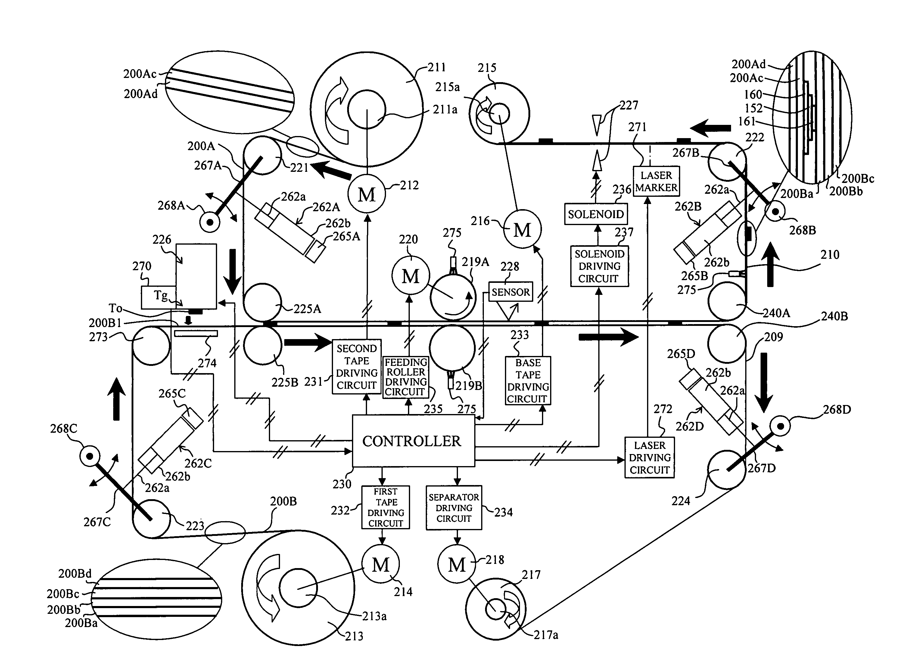
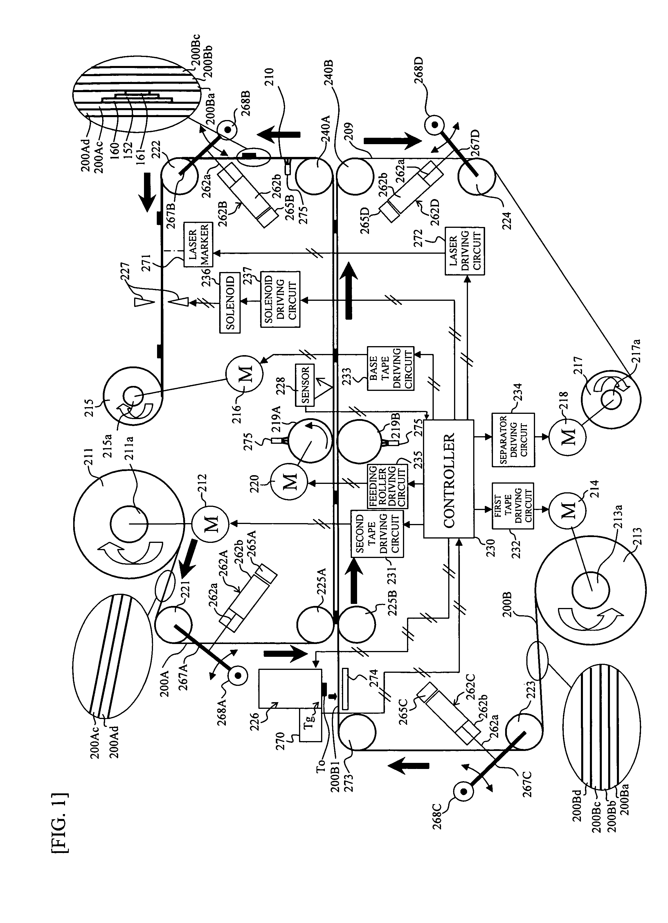
[0066]FIG. 1 is a conceptual diagram briefly showing an overall general structure of a tag tape roll manufacturing apparatus of the present embodiment. In FIG. 1, the tag tape roll manufacturing apparatus produces a base tape 210 by inserting bonding a second tape 200A (structural details are discussed later) and a first tape 200B (structural details are discussed later) and inserting an RFID tag Tg which is provided with an RFID circuit element To inserted between the two tapes, and manufactures a base tape roll 215 by winding the base tape 210.

[0067]That is, the tag tape manufacturing apparatus comprises a second tape roll 211 formed by the wound second tape 200A, a second tape shaft driving motor 212 for driving the second tape roll 211, a first tape roll 214 formed by the wound first tape 200B, a second ...

second embodiment

[0207]Note that although the tension control adds tension in the pulling direction of the first tape 200B as described above, the disclosure is not limited to this arrangement inasmuch as tension may be added to both the first tape 200B and the second tape 200A to provide a tension difference between the tension added to the first tape 200B and the tension added to the second tape 200A. In this case the tension added to the first tape 200B is greater than the tension added to the second tape 200A, and is controlled to a suitable value to lengthen the first tape 200B to be longer than the second tape 200A by the amount 2πt only. In this case as well, similar advantages to those of the second embodiment are provided.

[0208]Tension control for reducing the tension in the pulling direction may be performed as the position in the diameter direction of the roll become farther from the center in the diameter direction, and tension control for increasing tension in the pulling direction may ...

third embodiment

[0211]The following describes the present disclosure with reference to accompanying drawings.

[0212]FIG. 37 is a conceptual diagram showing an overall general structure of the tag tape roll manufacturing apparatus according to the present embodiment, and corresponds to FIG. 1 described above. FIG. 38 is a conceptual side view showing the condition the first tape 200B and the second tape 200A are bonded with the RFID tag Tg interposed therebetween in the present embodiment, and corresponds to FIGS. 2 and 5 above. Note that parts in FIGS. 1, 2, and 5 similar to parts in FIGS. 37 and 38 have the same reference number, and are not described further.

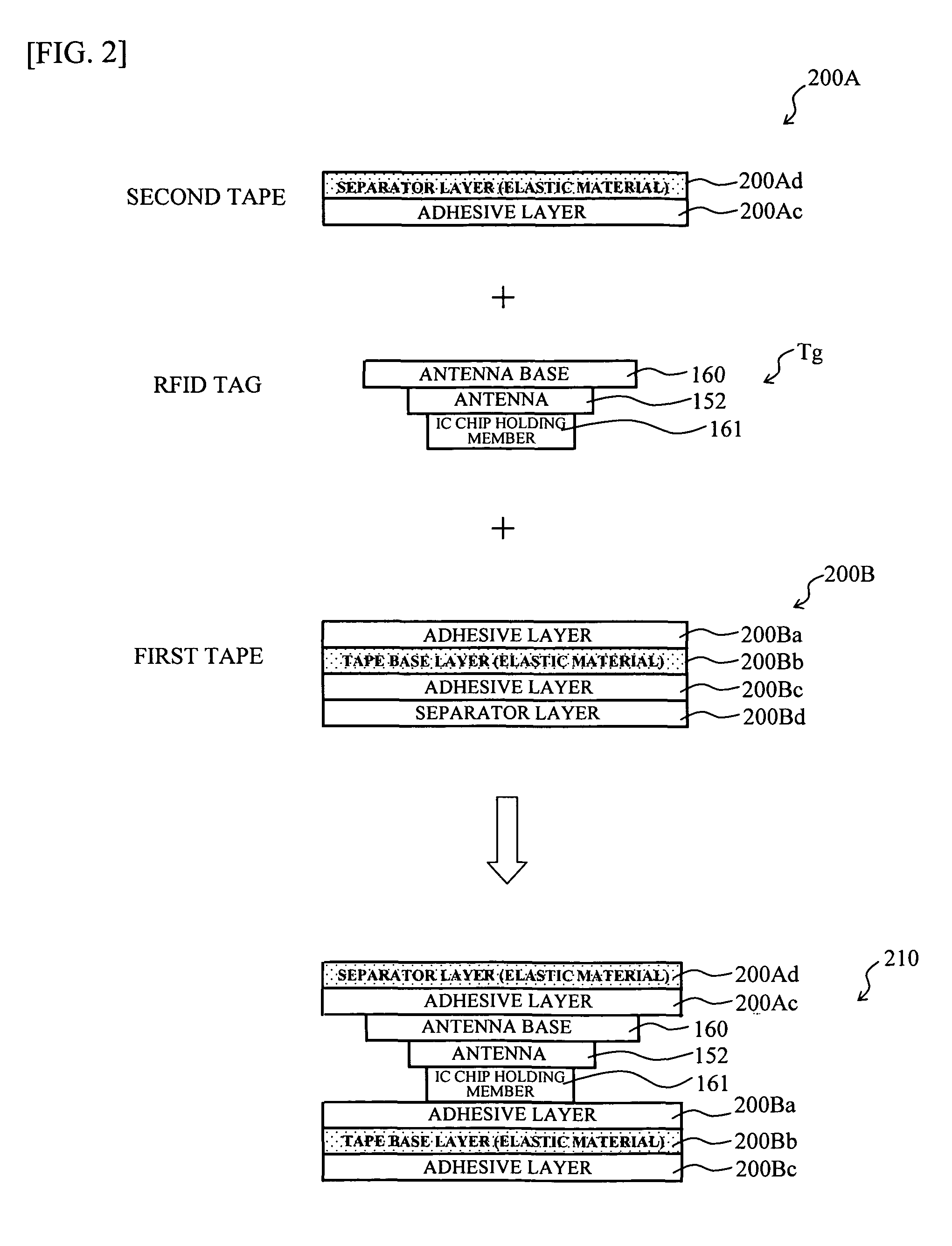
[0213]In FIGS. 37 and 38 the second tape 200A has a four-layer structure similar to FIG. 5 configured by sequentially laminating a separator layer 200Ad, adhesive layer 200Ac formed of a suitable adhesive, tape base layer 200Ab, and adhesive layer 200Aa. The first tape 200B also has a four-layer structure similar to FIG. 5 configured by sequen...


PUM

PropertyMeasurementUnit
thickness taaaaaaaaaaa

Abstract

This disclosure discloses a tag label producing apparatus comprising: a printing device; a transmitting/receiving device that performs information transmission/reception; a feeding device that feeds said tag medium; a coordination control portion; a communication determining portion that determines whether or not information transmission/reception has succeeded; and a decision portion that decides a feeding-stop condition for stopping feeding based on a feeding condition for the transmission/reception, and a feeding-condition for printing to a print area; wherein: said coordination control portion controls in coordination operations of said feeding device, said transmitting/receiving device, and said printing device so as to stop feeding based on said feeding-stop condition decided by said decision portion and to perform retry of said information transmission/reception when said communication determining portion determines that said information transmission/reception has failed.

Description

CROSS-REFERENCE TO RELATED APPLICATIONS[0001]This is an application PCT / JP2007 / 61762, filed Jun. 11, 2007, which was not published under PCT article 21(2) in English and claims the benefits of Japanese Patent application No. 2006-161744 filed Jun. 12, 2006, and No. 2006-353042 filed Dec. 27, 2006.BACKGROUND[0002]1. Field[0003]The present disclosure relates to a tag tape which has an RFID circuit element for storing information, a tag tape roll of the tag tape wound in the form of a roll, and an RFID label produced using this tag tape and tag tape roll.[0004]2. Description of the Related Art[0005]There are known RFID (radio frequency identification) systems for contactless (electromagnetic coupling method using a coil, electromagnetic induction method, or electromagnetic wave method) transmitting and receiving of information to / from an RFID tag circuit element for storing information.[0006]For example, JP, A, 2004-333651 is known to disclose a tag label producing apparatus for produc...

Claims


Application Information

Patent Timeline
Patent Type & Authority Patents(United States)
IPC IPC(8): H04Q5/22
CPCB31D1/021B31D1/027B31D1/028Y10T156/10G06K19/07718G06K19/0776
Inventor HIOKI, HITOMIOHTA, KIYOICHINAGAE, TSUYOSHIYAMAGUCHI, KOSHIROOHASHI, TSUYOSHI
Owner BROTHER KOGYO KK
Why Eureka
Try Eureka