
Exposure method, exposure apparatus, and device manufacturing method

a technology of exposure apparatus and manufacturing method, which is applied in the direction of photomechanical treatment, printing, instruments, etc., can solve the problems of faulty exposure such as defects, deterioration or damage of film on the surface of the object (the member) on which the liquid immersion area is formed, and decrease the exposure accuracy, so as to prevent the exposure of foreign substances. , the effect of suppressing the adhesion of foreign substances

Active Publication Date: 2011-11-22
NIKON CORP
View PDF105 Cites 6 Cited by
  • Summary
  • Abstract
  • Description
  • Claims
  • Application Information

AI Technical Summary

Benefits of technology

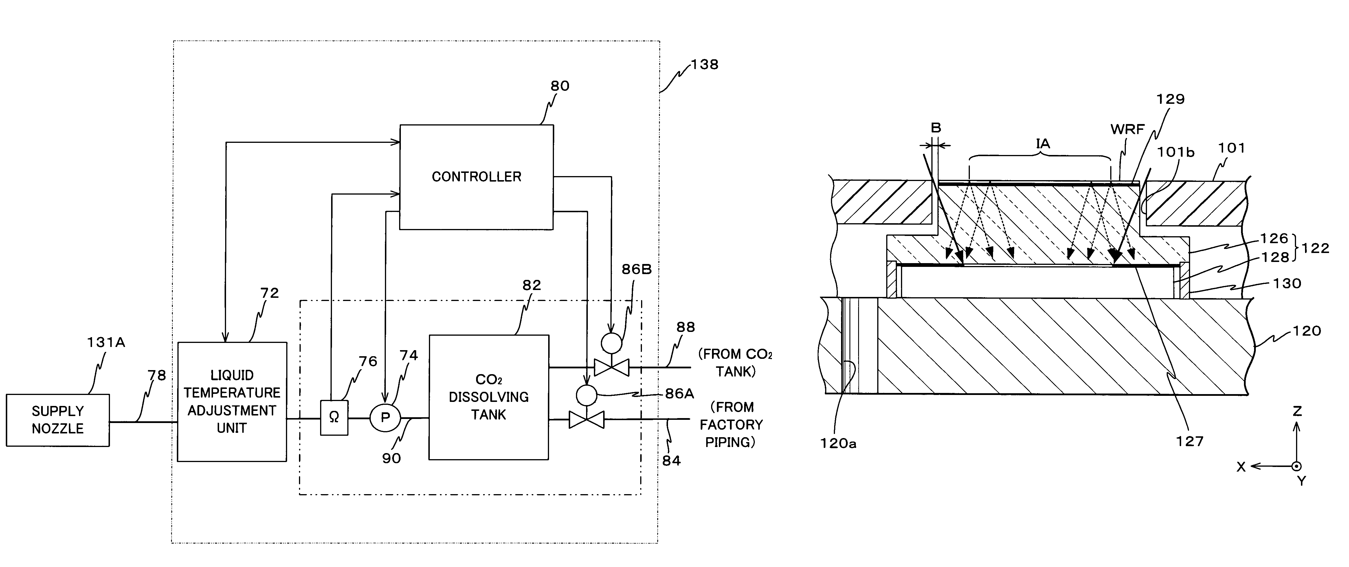
[0013]According to this method, by dissolving the predetermined substance and reducing the specific resistance of the liquid, the liquid immersion area can be formed on the film formed on the object with the liquid whose specific resistance is reduced. Therefore, the charge of the liquid is prevented or effectively suppressed, and generation of dielectric breakdown of the film on the object where the liquid immersion area is formed can be effectively suppressed. Accordingly, by performing the exposure in which the exposure light is irradiated on the object via the liquid of which the charge is prevented or effectively suppressed and a predetermined pattern is formed, the pattern can be formed on the object with good precision for over a long period of time.
[0015]According to this apparatus, the liquid immersion device has the mixing mechanism that mixes and dissolves the predetermined substance for adjusting specific resistance of the liquid, which is supplied onto the liquid repellent film on the surface of the member placed on the light emitting side of the optical member, and the liquid immersion area is formed by supplying the liquid in which the predetermined liquid is dissolved onto the liquid repellent film. Therefore, the specific resistance of the liquid can be reduced so that the charge of the liquid is prevented or effectively suppressed, and generation of dielectric breakdown of the liquid repellent film where the liquid immersion area is formed can be effectively suppressed. Accordingly, measurement with high precision can be executed by the sensor for over a long period of time, and by performing the exposure in which the exposure beam is irradiated on the object via the liquid with the measurement results being reflected, exposure with high precision can be performed for over a long period of time.
[0017]According to this apparatus, the liquid immersion device has a mixing mechanism that mixes and dissolves, in the liquid to be supplied onto the predetermined film formed on the object mounted on the object stage, a predetermined substance for adjusting specific resistance of the liquid, and the liquid immersion device forms the liquid immersion area on the film on the object with the liquid in which the predetermined liquid is dissolved. Therefore, with the liquid whose specific resistance has been reduced, the liquid immersion area is formed on the film formed on the object. As a consequence, the charge of the liquid is prevented or effectively suppressed, and generation of dielectric breakdown of the film member on the object where the liquid immersion area is formed can be effectively suppressed. Accordingly, by performing the exposure in which the exposure beam is irradiated on the object via the liquid whose charge is prevented or effectively suppressed so as to form a predetermined pattern, the pattern can be formed on the object with good precision.
[0018]Further, in a lithographic process, by using the exposure method of the present invention, a pattern can be formed with good accuracy on an object. Therefore, according to a fourth aspect of the present invention, it can also be said that the present invention is a device manufacturing method including a lithographic process in which a device pattern is formed on the object using the exposure method of the present invention. Further, by using one of the first and second exposure apparatus of the present invention in the lithographic process, a pattern can be formed on an object with good precision. Therefore, according to a fifth aspect of the present invention, it can also be said that the present invention is a device manufacturing method including a lithographic process in which a device pattern is formed on the object using one of the first and second exposure apparatus of the present invention.
[0020]According to this method, because electrical charge of the object is removed before the object is carried into the exposure apparatus, adherence of foreign substances can be suppressed, which can prevent exposure defects of the object.

Problems solved by technology

However, because purified water has high specific resistance, static electricity is generated due to friction with piping, nozzles or the like, and in the case the liquid immersion area is formed on the object (the member) with the charged purified water, there is a possibility that the object (the member) or a film on the surface of the object (the member) or both may be electrically charged.
In this case, the film on the surface of the object (the member) on which the liquid immersion area is formed could be deteriorated or damaged.
The deterioration of the film may cause unevenness in the optical properties of the deteriorated section and the section besides the deteriorated section, and / or may be the cause of water stains (water marks), which may consequently decrease the exposure accuracy.
Further, foreign substances or foreign matters may adhere on the surface of the object (the member) by the charge, and such foreign substances may contaminate the liquid (purified water), the wafer and the like, which may cause faulty exposure such as defects.
In this case, deterioration, modification or the like may occur on the film (a resist layer, and / or a top coat layer) on the object (the wafer), which could be the cause of defects being generated.
Further, in the case the object (the wafer) subject to exposure is charged, foreign substances may be adhered on the surface of the object (the wafer), and the liquid (purified water) and the object (the wafer) subject to exposure may be contaminated, which may cause faulty exposure such as defects.

Method used


Image

  • Exposure method, exposure apparatus, and device manufacturing method
  • Exposure method, exposure apparatus, and device manufacturing method
  • Exposure method, exposure apparatus, and device manufacturing method

Examples


Embodiment Construction

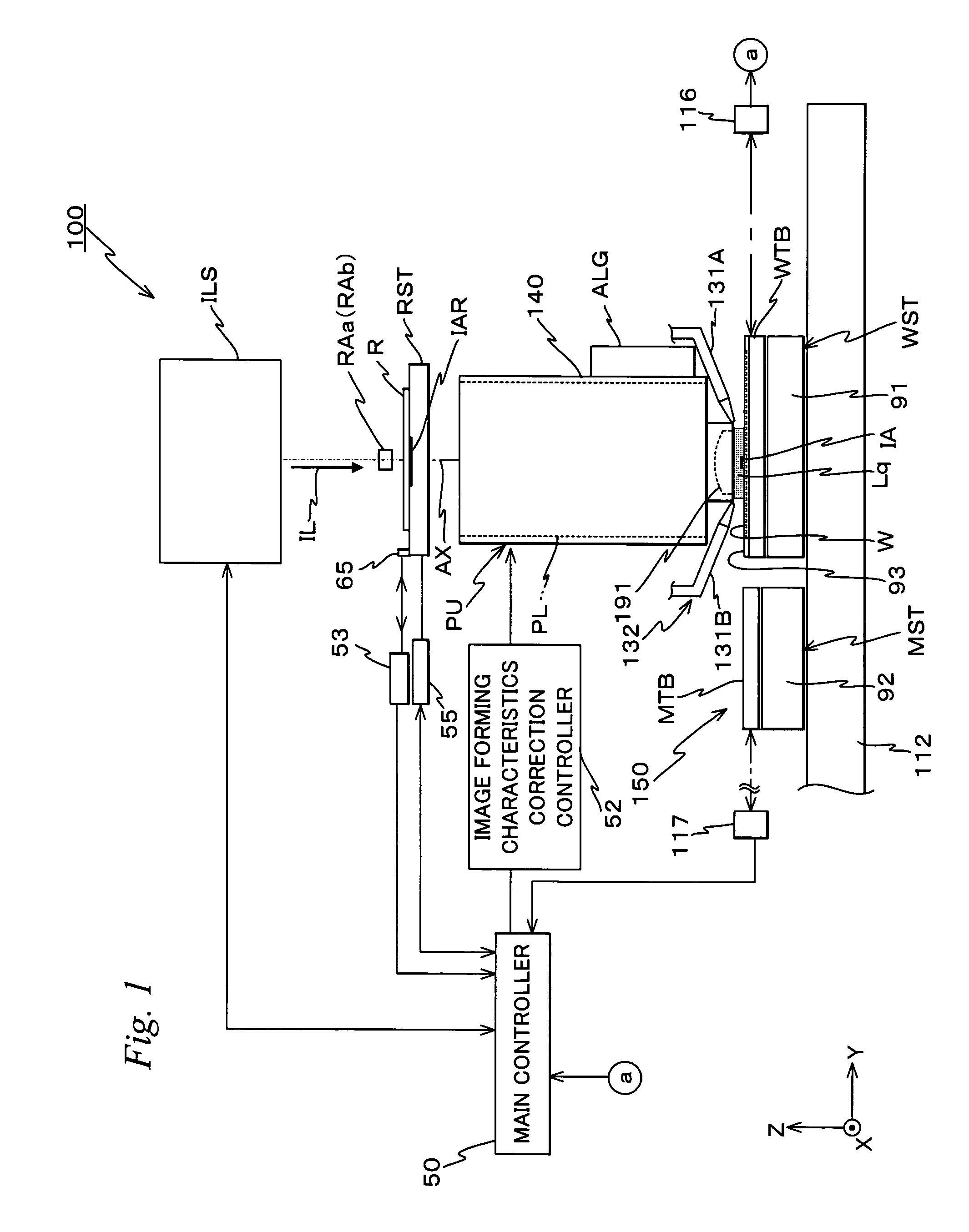
[0028]An embodiment of the present invention is described below, referring to FIGS. 1 to 6.

[0029]FIG. 1 is an entire view of an arrangement of an exposure apparatus 100 related to the embodiment. Exposure apparatus 100 is a scanning exposure apparatus based on a step-and-scan method, that is, the so-called scanner.

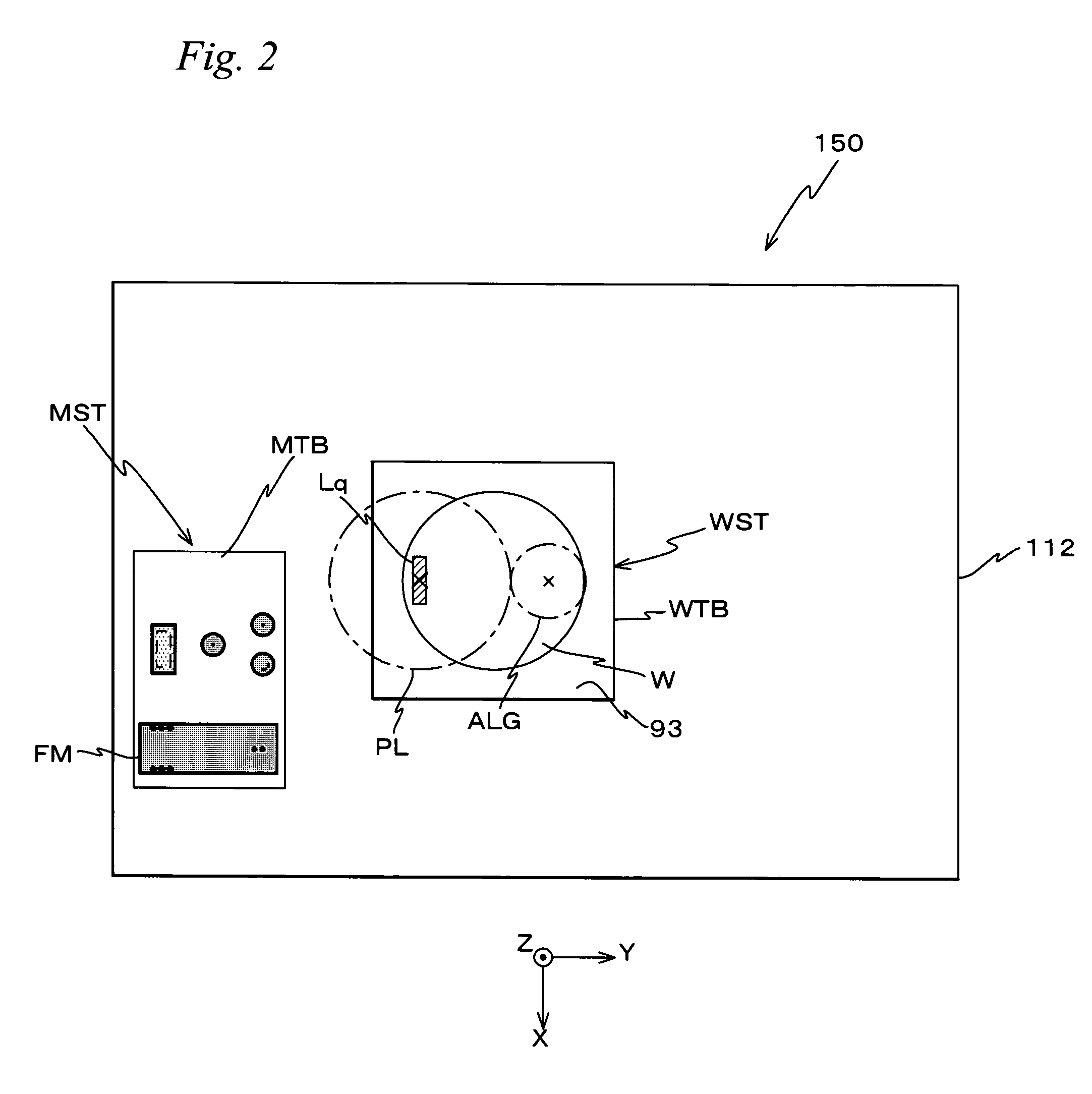
[0030]Exposure apparatus 100 is provided with an illumination system ILS, a reticle stage RST that holds a reticle R serving as a mask illuminated by an exposure illumination light IL serving as an energy beam from illumination system ILS and moves in a predetermined scanning direction (in this case, a Y-axis direction which is the lateral direction of the page surface in FIG. 1), a projection unit PU including a projection optical system PL that projects exposure illumination light IL emitted from reticle R onto a wafer W, a stage unit 150 including a measurement stage MST used on measurement for exposure, a control system of these parts, and the like.

[0031]As the light s...


PUM


Abstract

A liquid immersion device that has an mixing mechanism that mixes and dissolves a predetermined substance for adjusting specific resistance of the liquid, which is supplied onto a liquid repellent film on the surface of an object (member) of a projection optical system placed on the light emitting side of projection optical system, and an liquid immersion area is formed by supplying the liquid in which the predetermined liquid is dissolved onto the liquid repellent film.

Description

CROSS-REFERENCE TO RELATED APPLICATIONS[0001]This application is a continuation of International Application PCT / JP2006 / 308385, with an international filing date of Apr. 21, 2006, the disclosure of which is hereby incorporated herein by reference in its entirety, which was not published in English. This non-provisional application also claims the benefit of Provisional Application No. 60 / 751,208 filed Dec. 19, 2005, the disclosure of which is hereby incorporated herein by reference in its entirety.BACKGROUND OF THE INVENTION[0002]1. Field of the Invention[0003]The present invention relates to exposure methods, exposure apparatus, and device manufacturing methods, and more particularly to an exposure method and an exposure apparatus that are used when exposing an object via a liquid, and a device manufacturing method that uses the exposure method and the exposure apparatus in a lithographic process.[0004]2. Description of the Background Art[0005]Conventionally, in a lithographic proc...

Claims


Application Information

Patent Timeline
Patent Type & Authority Patents(United States)
IPC IPC(8): G03B27/42G03B27/54
CPCG03F7/70341G03F7/70858G03F7/2041H01L21/0273H01L21/0274G03F7/7095G03F7/70608
Inventor SHIRAISHI, KENICHIHOSHIKA, RYUICHIFUJIWARA, TOMOHARU
Owner NIKON CORP
Learn More