
Four-stroke engine

Active Publication Date: 2012-11-29
YAMAHA MOTOR CO LTD
View PDF22 Cites 5 Cited by
  • Summary
  • Abstract
  • Description
  • Claims
  • Application Information

AI Technical Summary

Benefits of technology

[0008]As described above, in the engine of U.S. Pat. No. 6,053,145, the fuel injector is disposed between the two intake ports or is disposed therebelow. However, in a casein which the fuel injector is disposed between the two intake ports, a space in which the fuel injector is disposed is ensured by greatly curving each intake port or by adjusting the distance between the two intake ports. Therefore, the shape or layout of the intake ports is restricted because of the fuel injector. Likewise, in a case in which the fuel injector is disposed below the intake ports, the shape or layout of the intake ports is restricted because of the fuel injector. However, if the intake port is greatly curved, fluid resistance at the intake port will increase, and the flow of intake air toward the combustion chamber will be obstructed. Therefore, the flow rate of air filled from the intake port into the cylinder will decrease, and the effect brought about by direct injection will decrease.
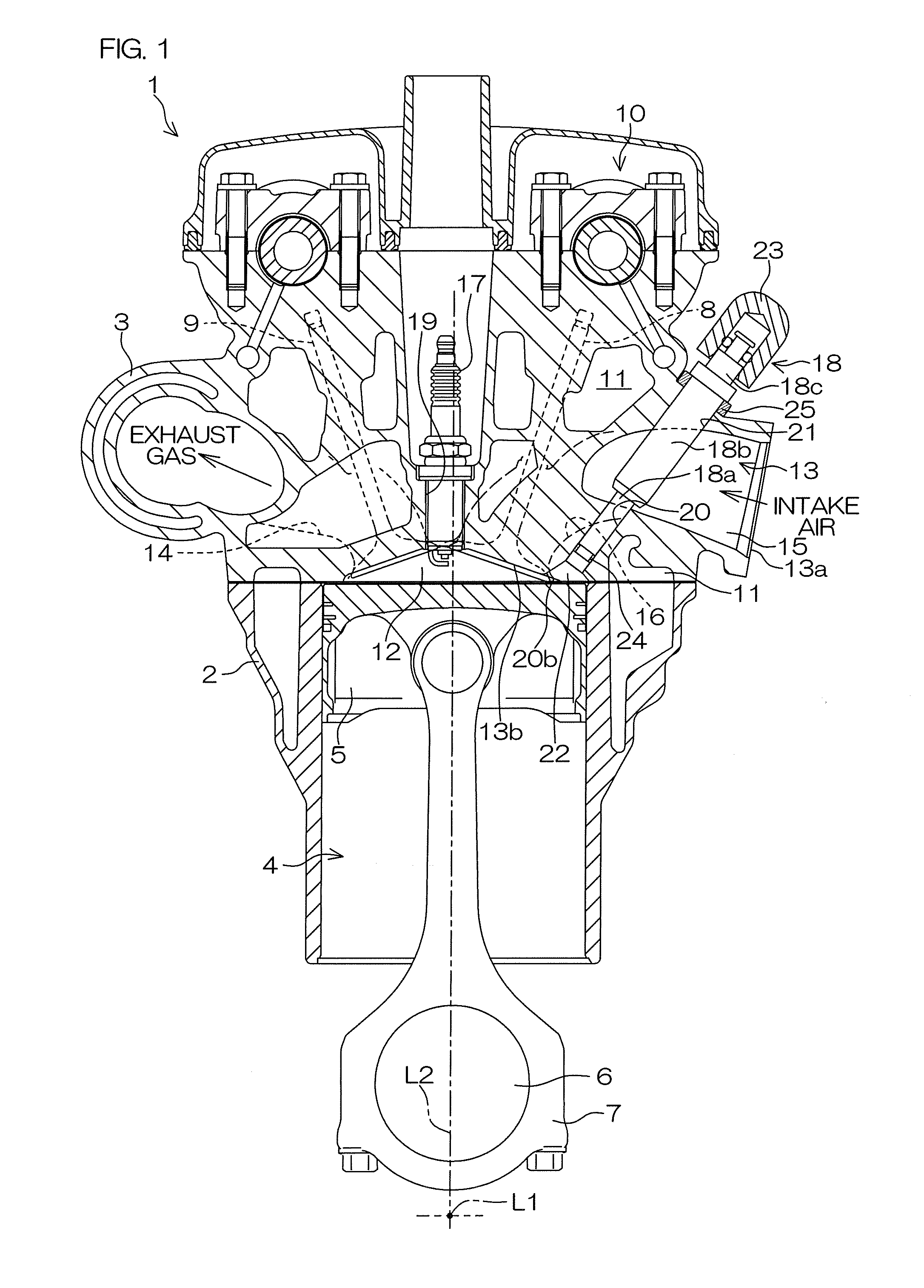
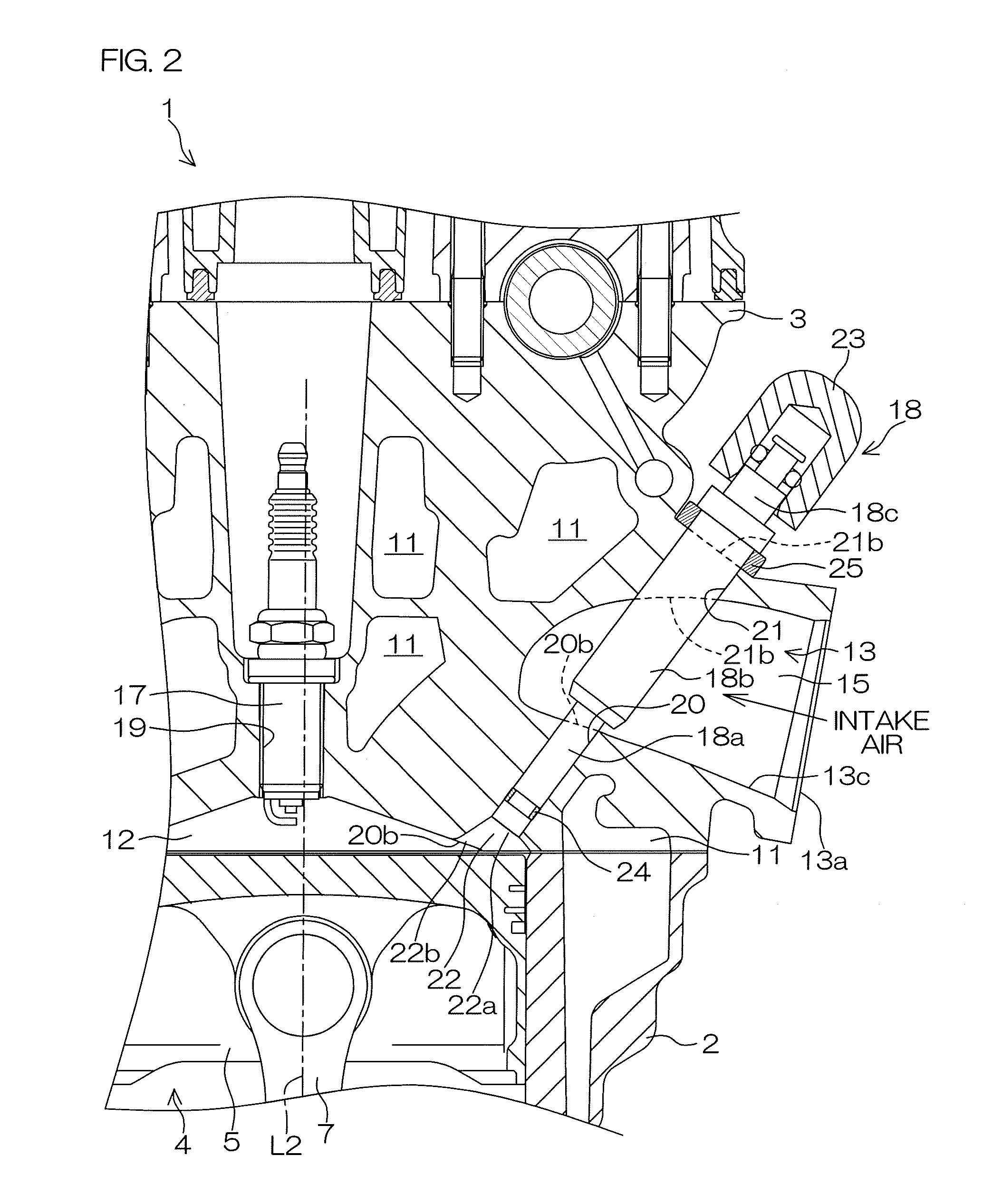
[0010]According to this arrangement, the housing hole that passes through the combustion chamber and through the intake port is located in the cylinder head, and at least a portion of the fuel injector is disposed at the intake port and at the housing hole. The fuel injector jets a fuel mist toward the combustion chamber. The fuel mist (i.e., liquid droplets of fuel) jetted from the fuel injector is supplied directly to the combustion chamber. Therefore, the inside of the cylinder can be cooled by evaporating the fuel in the cylinder. Therefore, the output and the fuel efficiency of the four-stroke engine are significantly improved. Additionally, at least a portion of the fuel injector is disposed at the intake port, and therefore the shape or layout of the intake port is not required to be changed in order to provide a space to dispose the fuel injector. Thus, an intake system has a high degree of freedom, and therefore the fluid resistance in the intake port can be decreased. Therefore, a decrease in the amount of air that flows from the intake port to the cylinder can be reduced.

Problems solved by technology

Therefore, the shape or layout of the intake ports is restricted because of the fuel injector.
Likewise, in a case in which the fuel injector is disposed below the intake ports, the shape or layout of the intake ports is restricted because of the fuel injector.
However, if the intake port is greatly curved, fluid resistance at the intake port will increase, and the flow of intake air toward the combustion chamber will be obstructed.

Method used


Image

  • Four-stroke engine
  • Four-stroke engine
  • Four-stroke engine

Examples


Embodiment Construction

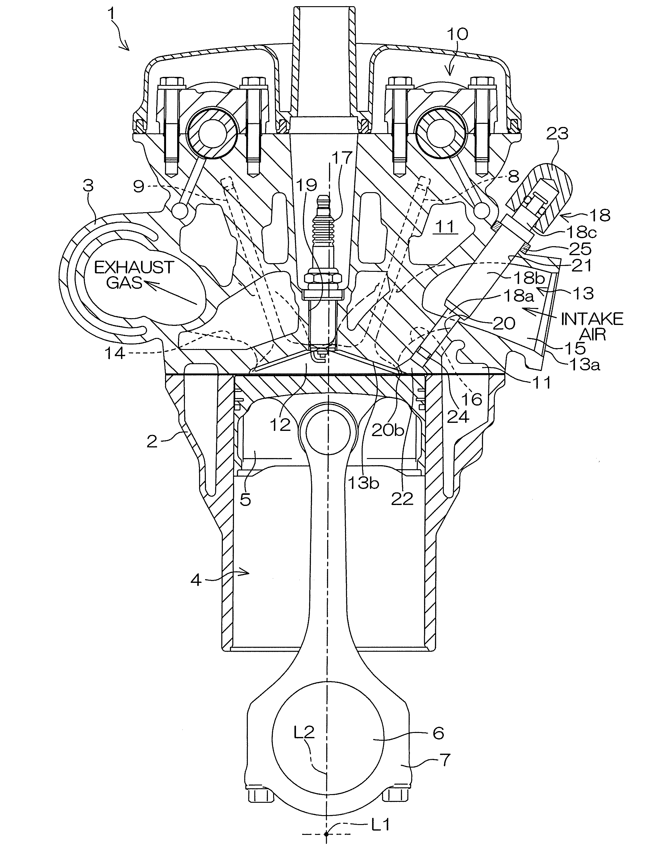
[0035]FIG. 1 is a sectional view of an engine 1 according to a first preferred embodiment of the present invention. FIG. 2 is an enlarged view of a portion of FIG. 1. In the following description, a direction in which a rotational axis L1 of a crankshaft 6 extends (i.e., a direction perpendicular to the plane of the sheet of paper of the drawing) is defined as a front-rear direction, and a direction in which a central axis L2 of a cylinder perpendicular to the rotational axis L1 extends (i.e., an up-down direction in the plane of the sheet of paper of the drawing) is defined as an up-down direction. However, this direction definition is one example, and the direction in which the rotational axis L1 extends may be a direction other than the front-rear direction.

[0036]The engine 1 is a four-stroke engine (internal combustion engine). The engine 1 may be mounted in a vehicle, such as an automobile or a motorcycle, or may be mounted in a vessel, or may be mounted in other devices. For e...


PUM


Abstract

A four-stroke engine includes a cylinder head in which a combustion chamber, an intake port that communicates with the combustion chamber, and a housing hole that passes through the combustion chamber and through the intake port are provided, and a fuel injector that supplies a mist of fuel directly to the combustion chamber by jetting the mist of fuel toward the combustion chamber. The fuel injector includes at least a portion that is disposed at the intake port and at the housing hole.

Description

BACKGROUND OF THE INVENTION[0001]1. Field of the Invention[0002]The present invention relates to a four-stroke engine.[0003]2. Description of the Related Art[0004]A direct-injection engine is known in which liquid fuel is supplied directly to a combustion chamber so as to improve its output and fuel efficiency.[0005]In the direct-injection engine, fuel is evaporated in a cylinder, and, as a result, the inside of the cylinder is cooled. Therefore, the output of the engine can be improved by increasing the amount of air with which the cylinder is filled. In addition, the temperature of the inside of the cylinder decreases, and therefore knocking can be prevented. Therefore, fuel efficiency can be improved by increasing the compression ratio of an air-fuel mixture.[0006]U.S. Pat. No. 6,053,145 discloses an engine in which liquid fuel is supplied directly to a combustion chamber. In the engine of U.S. Pat. No. 6,053,145, a fuel injector that jets fuel is disposed near intake ports. Two ...

Claims


Application Information

Patent Timeline
IPC IPC(8): F02M69/04
CPCF02B23/104Y02T10/125F02M61/14Y02T10/12
Inventor WATANABE, TAKAHIROTAKASU, DAISUKE
Owner YAMAHA MOTOR CO LTD
Learn More