Workpiece transfer apparatus and electronic component transfer apparatus

a technology of electronic components and conveying apparatuses, which is applied in the direction of charge manipulation, instruments, furniture, etc., can solve the problems of residual pressure being released even with a low positioning accuracy, and the residual pressure cannot be sufficiently released, so as to increase the efficiency of producing workpieces, increase the conveying speed of workpiece conveying apparatuses, and increase the efficiency of production

Active Publication Date: 2011-11-08
MURATA MFG CO LTD
View PDF18 Cites 6 Cited by
  • Summary
  • Abstract
  • Description
  • Claims
  • Application Information

AI Technical Summary

Benefits of technology

[0020]In view of the foregoing problems, the disclosed workpiece conveying apparatus and electronic-component conveying apparatus solve the drawbacks associated with the above-described conventional art, wherein the workpiece conveying apparatus has a structure in which a high-pressure gas is jetted through an exhaust hole into a through hole containing a workpiece to dismount the workpiece from the through hole. The workpiece conveying apparatus can solve the above-described problem associated with residual pressure, prevent a workpiece from unintentionally jumping out, and accelerate the conveying process including a process of dismounting a workpiece.
[0024]With these features, the fluid resistance can be decreased when the compressed gas is jetted, whereby the flow rate of the compressed gas can be increased. This enables the workpiece to be reliably dismounted from the through hole. Further, the operation time from the beginning to the end of jetting of compressed gas can be decreased. Accordingly, the operation speed of the workpiece conveying apparatus can be increased.
[0026]If the exhaust hole has a plurality of the nozzle sections, the workpiece will be placed on the portion between the plurality of nozzle sections. Thus, the workpiece is less likely to interfere with the peripheries of the openings of the nozzle sections. If the plurality of nozzle sections include first and second nozzle sections and the first and second nozzle sections are arranged such that a part of the workpiece is positioned on a portion between the first and second nozzle sections, the workpiece moves on the portion between the first and second nozzle sections. Thus, the workpiece is less likely to interfere with the peripheries of the openings of the first and second nozzle sections.
[0027]The conveying table preferably is disk-shaped having a central axis. The driving unit drives and rotates the conveying table about the central axis. In this case, the workpiece disposed in the through hole is conveyed in the circumferential direction of the conveying table with the rotation of the conveying table. Because the conveying path extends in the circumferential direction of the disk-shaped conveying table, the workpiece conveying apparatus can be made compact, and the installation space thereof can be reduced.
[0031]Thus, residual pressure is less likely to be generated when the conveying table is rotated and closes the exhaust hole. Thus, the subsequent workpiece can be prevented from undesirably jumping out because of residual pressure, and the conveying speed of the workpiece conveying apparatus can be increased. Accordingly, the efficiency of producing workpieces can be increased.

Problems solved by technology

There is a problem in that, however, even if the length of the waiting time is increased, residual pressure cannot be sufficiently released.
That is, residual pressure can be released even with a low positioning accuracy of the through hole in the conveying direction.

Method used


Image

  • Workpiece transfer apparatus and electronic component transfer apparatus
  • Workpiece transfer apparatus and electronic component transfer apparatus
  • Workpiece transfer apparatus and electronic component transfer apparatus

Examples


Embodiment Construction

Reference Numerals

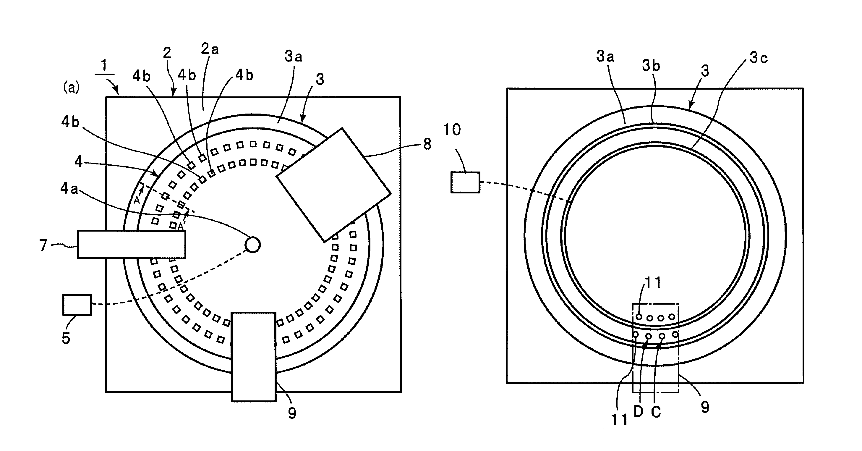
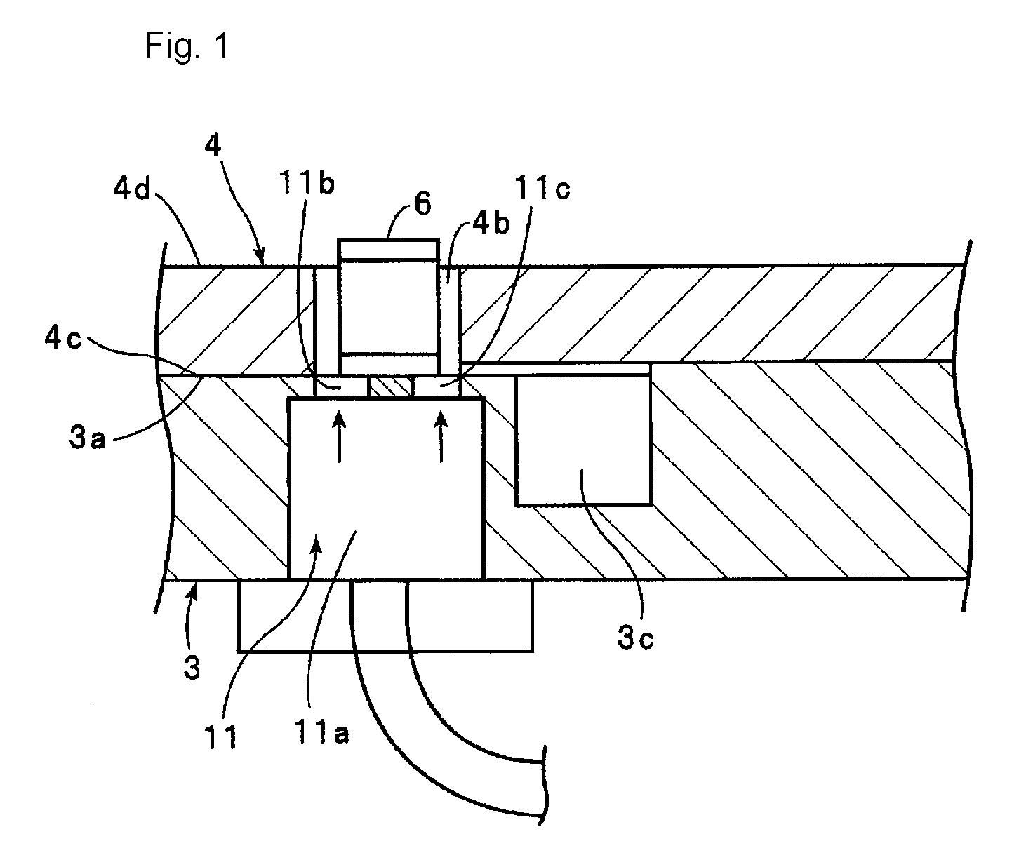
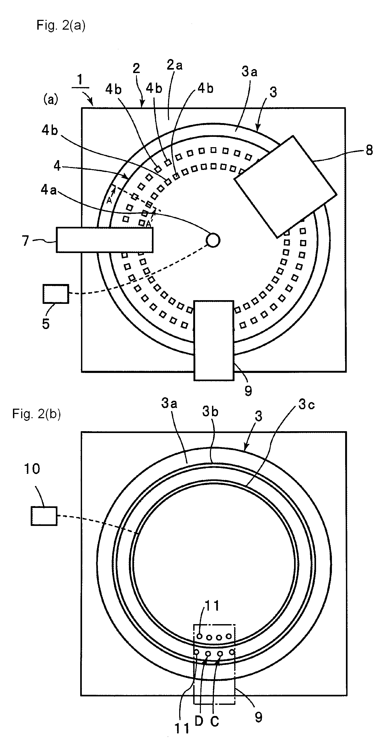
[0043]1: electronic-component conveying apparatus[0044]2: base plate[0045]3: conveying stage[0046]3a: conveying surface[0047]3b, 3c: vacuum recess[0048]4: conveying table[0049]4a: central axis[0050]4b: through hole[0051]4c: first surface[0052]4d: second surface[0053]4e: vacuum groove[0054]5: driving unit[0055]6: electronic component[0056]7: electronic-component supplying unit[0057]8: property measuring device[0058]9: dismounting unit[0059]10: vacuum source[0060]11: exhaust hole[0061]11a: main exhaust-hole section[0062]11b, 11c: nozzle section[0063]11d: retaining section[0064]24b, 34b, 44b: through hole

[0065]Now, the present disclosure will be clarified by explaining specific embodiments with reference to the drawings.

[0066]FIGS. 2(a) and (b) are, respectively, a schematic front view of an electronic-component conveying apparatus according to an embodiment, and a schematic front view of the same excluding a conveying table, which will be described below.

[0067]An ele...


PUM


Abstract

A workpiece conveying apparatus for conveying a workpiece disposed in a through hole in a conveying table allows the workpiece to be reliably dismounted from the through hole using compressed gas, suppresses the workpiece from unintentionally jumping out because of residual pressure of the compressed air, and increases the conveying efficiency. In an electronic-component conveying apparatus, a conveying table is arranged to face a conveying surface of a conveying stage, with an electronic component disposed in a through hole in the conveying table. When the conveying table is rotated, the electronic component is conveyed. The conveying surface has an exhaust hole at a position where the electronic component is to be dismounted. The total area of the opening of the exhaust hole in the conveying table is larger than the area of the surface of the electronic component facing the conveying surface of the conveying stage.

Description

CROSS-REFERENCE TO RELATED APPLICATIONS[0001]This is a continuation under 35 U.S.C. §111(a) of PCT / JP2007 / 059362 filed May 2, 2007, and claims priority of JP2006-144558 filed May 24, 2006, both incorporated by reference.[0002]This application is related to U.S. Ser. No. 12 / 246,079, filed Oct. 6, 2008, (P / 1320-238), also incorporated by reference.BACKGROUND[0003]1. Technical Field[0004]The present disclosure relates to a workpiece conveying apparatus for conveying multiple workpieces such as chip electronic components. More specifically, the present disclosure relates to a workpiece conveying apparatus and an electronic-component conveying apparatus of the type that conveys workpieces by moving a conveying table, which has through holes serving as container portions for containing workpieces, over a conveying stage.[0005]2. Background Art[0006]Conventionally, in manufacturing chip electronic components, after chip electronic components are fabricated and inspected for their propertie...

Claims


Application Information

Patent Timeline
Patent Type & Authority Patents(United States)
IPC IPC(8): B65G49/00
CPCG01R31/2893H05K13/021B65G47/80
Inventor SASAOKA, YOSHIKAZUTAKEUCHI, SATORU
Owner MURATA MFG CO LTD
Why Eureka
Try Eureka