Clinical analyzer having a variable cycle time and throughput

a technology of cycle time and throughput, applied in the field of clinical analyzers, can solve problems such as inefficiency of consumables and operational inefficiencies

Inactive Publication Date: 2011-11-29
SIEMENS HEALTHCARE DIAGNOSTICS INC
View PDF12 Cites 10 Cited by
  • Summary
  • Abstract
  • Description
  • Claims
  • Application Information

AI Technical Summary

Problems solved by technology

There are inherent operational and consumable inefficiencies if an analyzer is capable of performing a relatively higher number of assays per hour, but if the assay load demand is a relatively lower number.

Method used


Image

  • Clinical analyzer having a variable cycle time and throughput
  • Clinical analyzer having a variable cycle time and throughput
  • Clinical analyzer having a variable cycle time and throughput

Examples


first embodiment

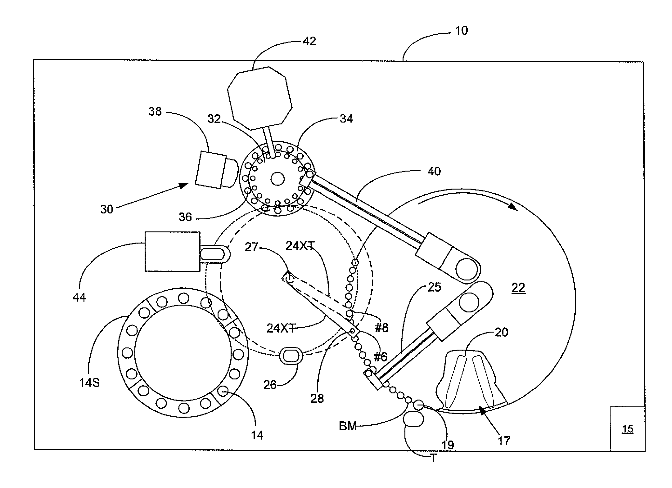
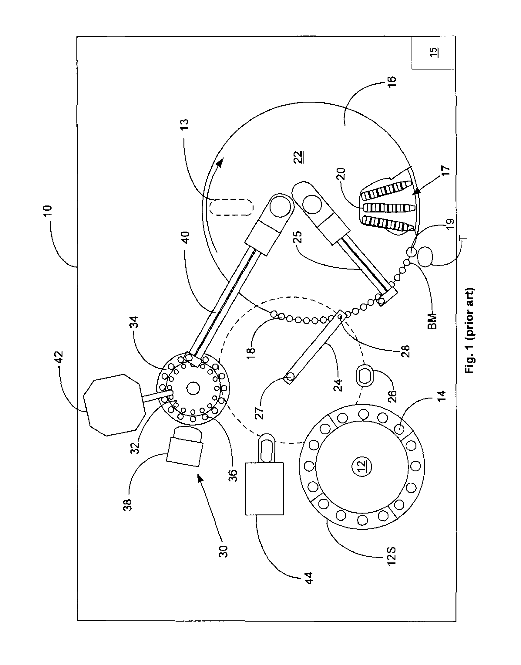
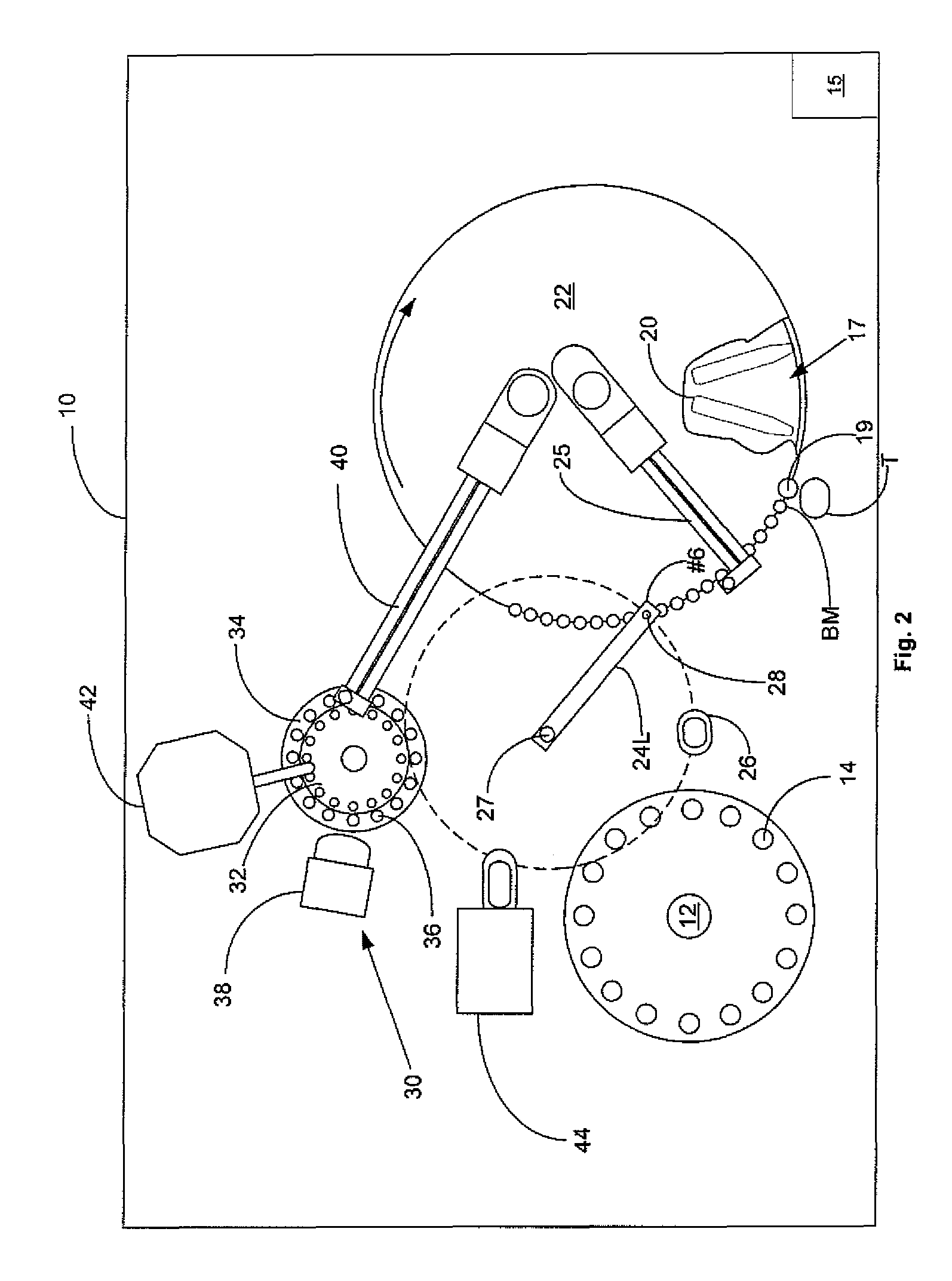
[0030]FIG. 2 is a schematic plan view of the clinical analyzer of FIG. 1, illustrating a “longer” sampling probe arm 24L adapted for dispensing sample from probe 28 into a reaction cuvette 18 at a first location indicated as #6 in order to achieve a relatively lower analyzer 10 throughput as a consequence of a relatively lower number of samples being presented to the analyzer for processing. In this embodiment, cuvette reaction carousel 16 is rotated clockwise, step-wise between next adjacent cavity 19 locations at a first illustrative “longer” cycle time of about 14.4 sec. between rotations. Sampling probe arm 24L is “longer” because a longer reach is required to dispense sample into a reaction cuvette 18 at location #6 in comparison to being able to dispense sample into a reaction cuvette 18 at a second location described hereinafter, indicated as #8 and corresponding to a relatively higher “cycle time” of about 7.2 seconds thereby increasing throughput of analyzer 10. This first ...

second embodiment

[0031]FIG. 3 is a schematic plan view of the clinical analyzer of FIG. 1, illustrating sampling probe arm 24S adapted for dispensing sample from probe 28 into a reaction cuvette 18 at a second sample dispensing location indicated as #8 corresponding to a relatively higher analyzer 10 throughput. In this embodiment, cuvette reaction carousel 16 is rotated clockwise, step-wise between next adjacent cavity 19 locations at a second illustrative cycle time of about 7.2 sec. This second illustrative cycle time is selected for producing a relatively faster analyzer throughput and is not restrictive for conducting the present invention. As in the first instance, cuvette reaction carousel 16 comprises three hundred (300) cavities 19 so that a total time of about 2,160 seconds (36 minutes or 0.6 hours) elapses between the time a cuvette 18 is formed at BM and the time that same cuvette 18 is disposed in trash T. As a consequence of these illustrative values, the assay throughput of analyzer 1...


PUM

PropertyMeasurementUnit
” cycle timeaaaaaaaaaa
timeaaaaaaaaaa
timeaaaaaaaaaa

Abstract

A clinical analyzer having the capability to operate at both a higher and lower throughput, depending upon the assay load demand experienced by the hospital or laboratory, so that analyzer throughput most closely matches assay demand.

Description

FIELD OF THE INVENTION[0001]The present invention relates to a clinical analyzer having a method for increasing throughput. In particular, the present invention provides a clinical analyzer with a sampling arm automated in synchronization with a variable cycle time reaction cuvette transport in order to increase analyzer throughput.BACKGROUND OF THE INVENTION[0002]Various types of analytical tests related to patient diagnosis and therapy can be performed by analysis of a liquid sample taken from a patient's infections, bodily fluids or abscesses. These assays are typically conducted with automated clinical analyzers onto which tubes or vials containing patient samples have been loaded. The analyzer extracts liquid sample from the vial and combines the sample with various reagents in special reaction cuvettes or tubes. Usually the sample-reagent mixture is incubated or otherwise processed before being analyzed. Analytical measurements are often performed using a beam of interrogating...

Claims


Application Information

Patent Timeline
Patent Type & Authority Patents(United States)
IPC IPC(8): G01N21/00G01N35/00G01N33/00G01N31/00G01N35/02
CPCG01N35/109G01N35/025Y10T436/11Y10T436/115831G01N2035/1093
Inventor KEGELMAN, JOSEPH E.CLAIR, KEVIN J.PARMER, JEFFREY K.BRODEUR, RICHARD G.EVERS, ALEXANDER V.LLOYD, MARK R.
Owner SIEMENS HEALTHCARE DIAGNOSTICS INC
Why Eureka
Try Eureka