Boat tiller restraining device

a technology of restraining device and tiller, which is applied in the direction of steering initiation, special purpose vessels, vessel construction, etc., can solve the problems of cumbersome use, inability to quickly or intuitively release when necessary, and the boat veering off course with undesirable effects,

Active Publication Date: 2011-12-06
CRAWFORD PETER JAMES
View PDF19 Cites 7 Cited by
  • Summary
  • Abstract
  • Description
  • Claims
  • Application Information

AI Technical Summary

Benefits of technology

[0036](h) To provide a tiller restraining device that is compact and can be permanently installed without taking up valuable space during use or storage;

Problems solved by technology

Without some method of restricting tiller movement, the rudder can quickly swing to one side or the other, causing the boat to veer off course with undesirable results.
The difficulty with these devices is that they occupy two hands for set-up or adjustment, and they cannot be released quickly or intuitively when necessary.
Unfortunately, in windy, foul-weather or crowded conditions the ability to make a quick-steering adjustment can be crucial.
Though somewhat effective, each of these contraptions would prove cumbersome and awkward to use within the crowded confines of smaller-sized boats that typically use tillers for steering.
In particular, they can obstruct the use of several important ropes that require frequent monitoring within the cockpit.
Additionally, when not in use, these awkward devices consume precious cockpit storage space, and they present an unsightly, incongruent effect on the neat lines of a sailing craft.
First, it takes time to activate, as the knob must be rotated several turns to engage or disengage the control rope.
Often frustrated by this operational requirement, the user tends to leave the knob partially tightened and simply overpowers it for every steering adjustment.
This use tends to wear on the control rope and allow the device to slip under normal water pressures acting upon the rudder.
Furthermore, the tensioning knob protrudes from the top of the device, where it has been known to dangerously snag critical ropes during quick sailing maneuvers.
However, this product also falls short.
This extended part can present a scraping hazard to the user, and can badly pinch a finger when closed in a hurry.
However, in practice, this increasing grip could be hazardous because the cams would not yield to excessive rudder forces that could cause rudder failure.
Furthermore, increasing tension on the control rope would make the cams increasingly difficult for the lever to disengage.
This requirement would diminish the convenience of the device and could slow steering reaction time.
Finally, installation of the product onto the tiller is complicated by the attachment of the two separate components that require careful alignment for proper operation.
(a) Both hands are occupied to operate the device while steering.
(b) The operator must focus attention on the device to locate it and to operate it effectively.
(c) The device does not lend itself to one-handed, minor steering corrections while in use.
(d) Working the device requires repeated or complex hand motions to rotate an adjustment knob or work a clamp.
(e) The device restrains the tiller too securely, so the tiller cannot be forced by hand pressure, and will not yield to excessive underwater rudder pressure.
(f) An upwardly-protruding part of the device can entangle operating lines on the boat, and can present a hazard to the user.
(h) Rigid poles or rods of the device are cumbersome and consume limited storage space when not in use.
(i) The mechanism presents a pinching hazard to the user.
(j) The device is ungainly and unpleasing to the eye.
Some of these disadvantages represent inconveniences, while others can slow reaction time and hinder boat operation, or become hazardous in rough conditions.
(j) To provide a tiller restraining device that is unobtrusive and aesthetically pleasing.

Method used


Image

  • Boat tiller restraining device
  • Boat tiller restraining device
  • Boat tiller restraining device

Examples


Embodiment Construction

Preferred Embodiment—FIGS. 1, 2, 3, 4 and 5

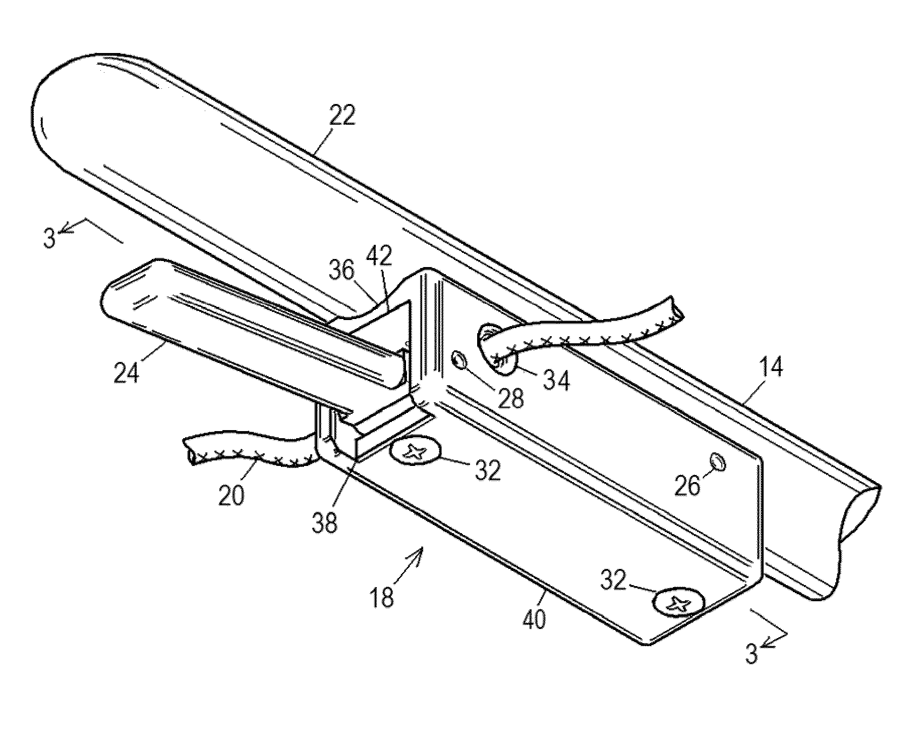
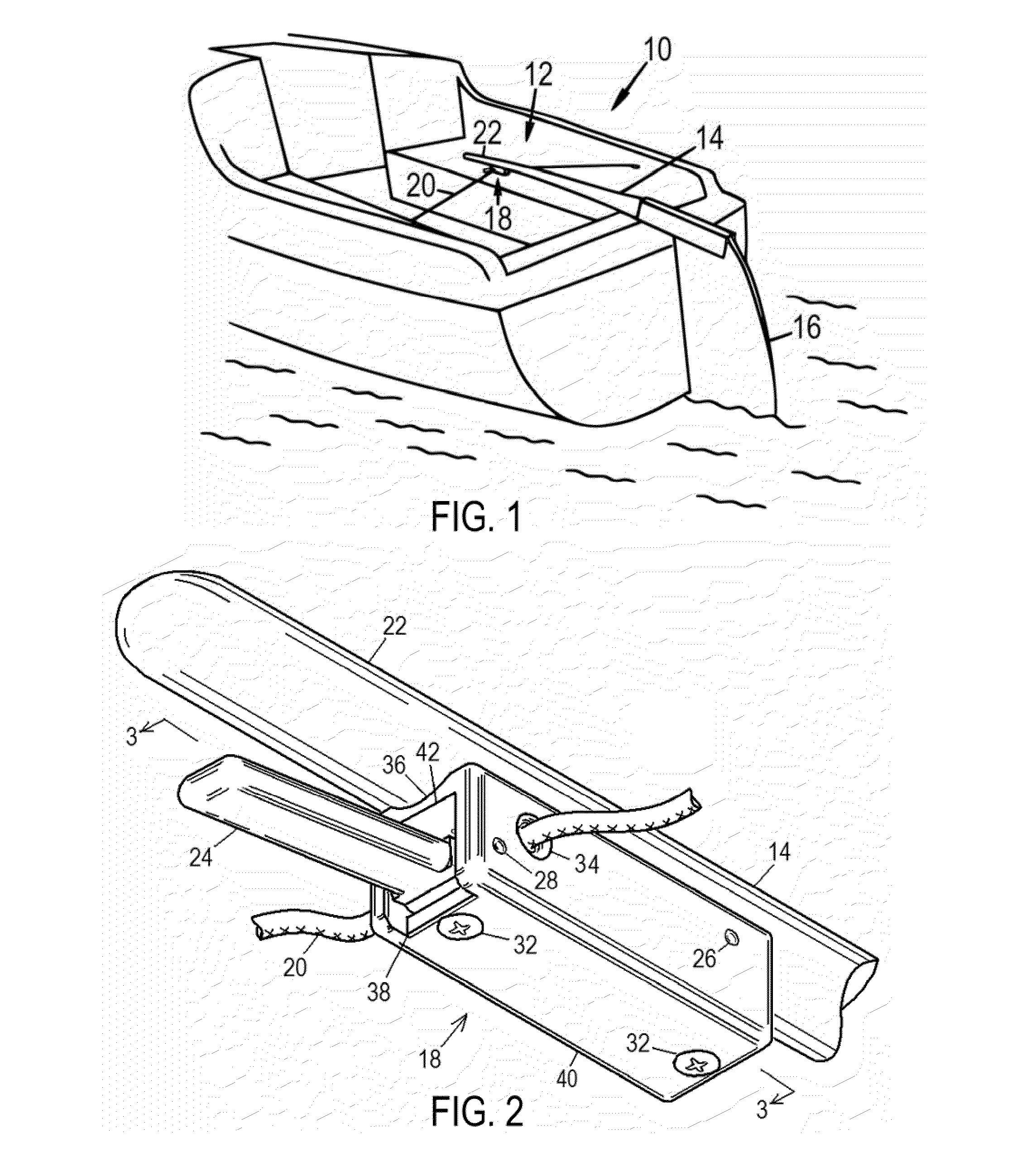
[0095]A preferred embodiment of the present boat tiller restraining device 18 is generally illustrated in perspective view FIG. 1. A sailboat 10 having a cockpit 12 is equipped with a pivotally mounted rudder 16 to control the direction of travel. The rudder 16, in turn, is controlled by a tiller arm 14 having a handle section 22, which is held by the helmsman or pilot when steering the boat. A small control rope 20 spans the cockpit 12, and is attached at each end to the sides of the boat 10 near the stern, meaning the back, or aft end of the boat. This rope may be fastened to the boat sides by any conventional means, such as a rope cleat, screw eye, padeye, shackle, etc. The rope 20 passes through a tiller restraining device generally designated 18, which is fixed to the underside of the tiller 14 near its handle section 22.

[0096]FIG. 2 is an enlarged perspective view of the tiller restraining device 18, which has a generally rectangular,...


PUM


Abstract

An improved tiller restraining device is provided for attachment to the underside of a boat's tiller to selectively control the position of the tiller and rudder. The device features a specialized mechanical clutch that grips or releases a control rope, which runs through the clutch and is secured across the cockpit. The device is operated with one hand by moving an integrated clutch lever upward to release the rope and allow free tiller movement, or downward to engage the rope and restrict tiller movement. Inside the device, a spring acts on the lever to pinch and bind the rope against the openings where the rope passes through the clutch housing. The spring and lever are aligned so they toggle, enabling the clutch to remain either engaged or disengaged with no additional controls.

Description

CROSS-REFERENCE TO RELATED APPLICATIONS[0001]Not ApplicableFEDERALLY SPONSORED RESEARCH[0002]Not ApplicableSEQUENCE LISTING OR PROGRAM[0003]Not ApplicableBACKGROUND OF THE INVENTION[0004]1. Field of Invention[0005]This invention generally relates to the steering of boats, specifically to an improved mechanical device that allows a single-handed pilot to quickly and easily restrain the position of the tiller and rudder at the stern of a boat.[0006]2. Prior Art[0007]Most smaller boats, especially sailboats, are steered with a rudder at the stern that is pivoted by a long arm called a tiller. The tiller extends into the steering area, or cockpit, for the sailor or pilot to use.[0008]When steering a boat single handedly, a sailor often needs to momentarily release the tiller to attend to other critical tasks, including changing sails, adjusting lines, preparing anchors, and retrieving needed articles from elsewhere on the boat. Without some method of restricting tiller movement, the rud...

Claims


Application Information

Patent Timeline
Patent Type & Authority Patents(United States)
IPC IPC(8): B63H25/00B63H25/10B63H25/04B63H25/34A44B11/25A44B17/00F16G11/00A44B1/04
CPCB63H25/10F16G11/04F16G11/06Y10T24/3938Y10T24/3936F16G11/101B63H2025/024B63H25/02
Inventor CRAWFORD, PETER JAMES
Owner CRAWFORD PETER JAMES
Why Eureka
Try Eureka