Drill chuck

Active Publication Date: 2011-12-06
ROHM GMBH & CO KG
View PDF17 Cites 35 Cited by
  • Summary
  • Abstract
  • Description
  • Claims
  • Application Information

AI Technical Summary

Benefits of technology

[0020]It is advantageous if the conical collar is formed with the locking seats of the retaining device, that is, if the retaining device and the detent device act in one plane.
[0021]The retaining device can be realized in an especially simple and therefore preferred manner if a locking spring arranged on t

Problems solved by technology

However, it has been determined in the case of this drill chuck that when it is used problems can occur with the manipulation of the loosening ri

Method used


Image

  • Drill chuck
  • Drill chuck
  • Drill chuck

Examples


Example

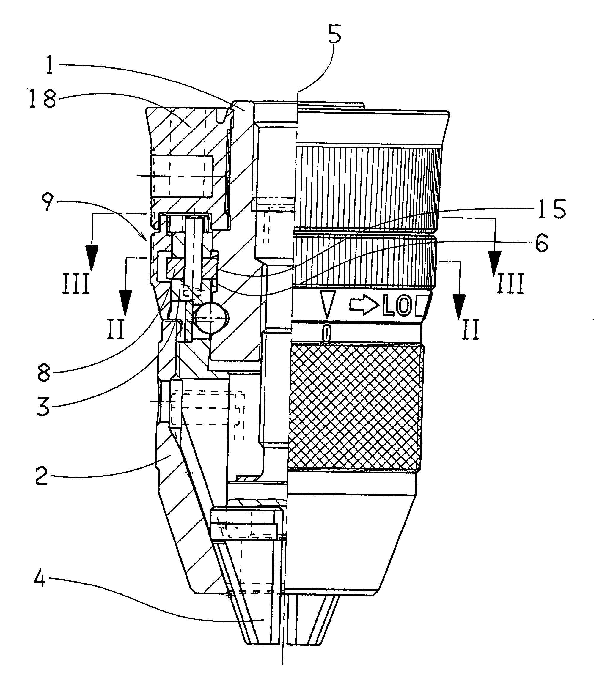
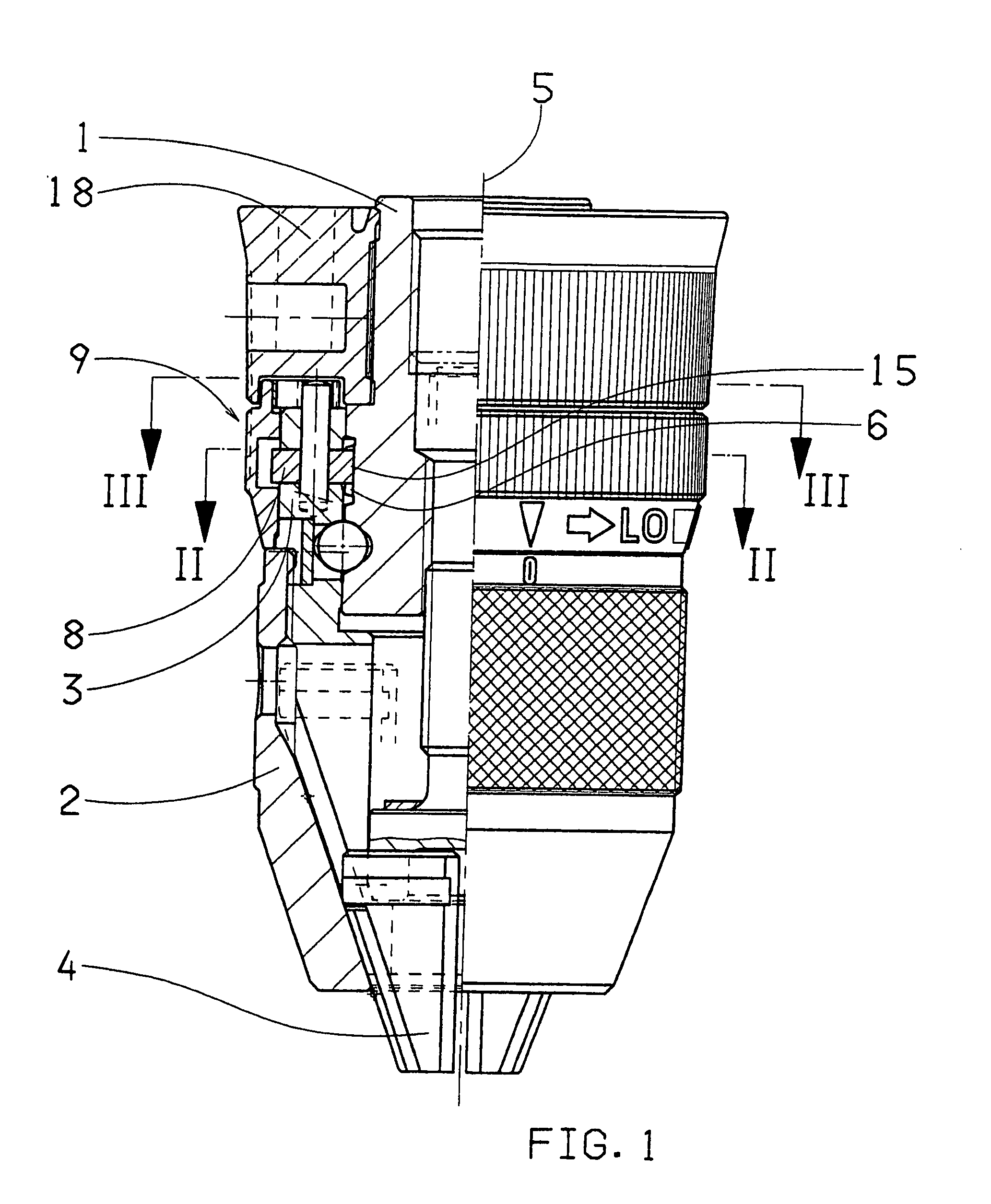
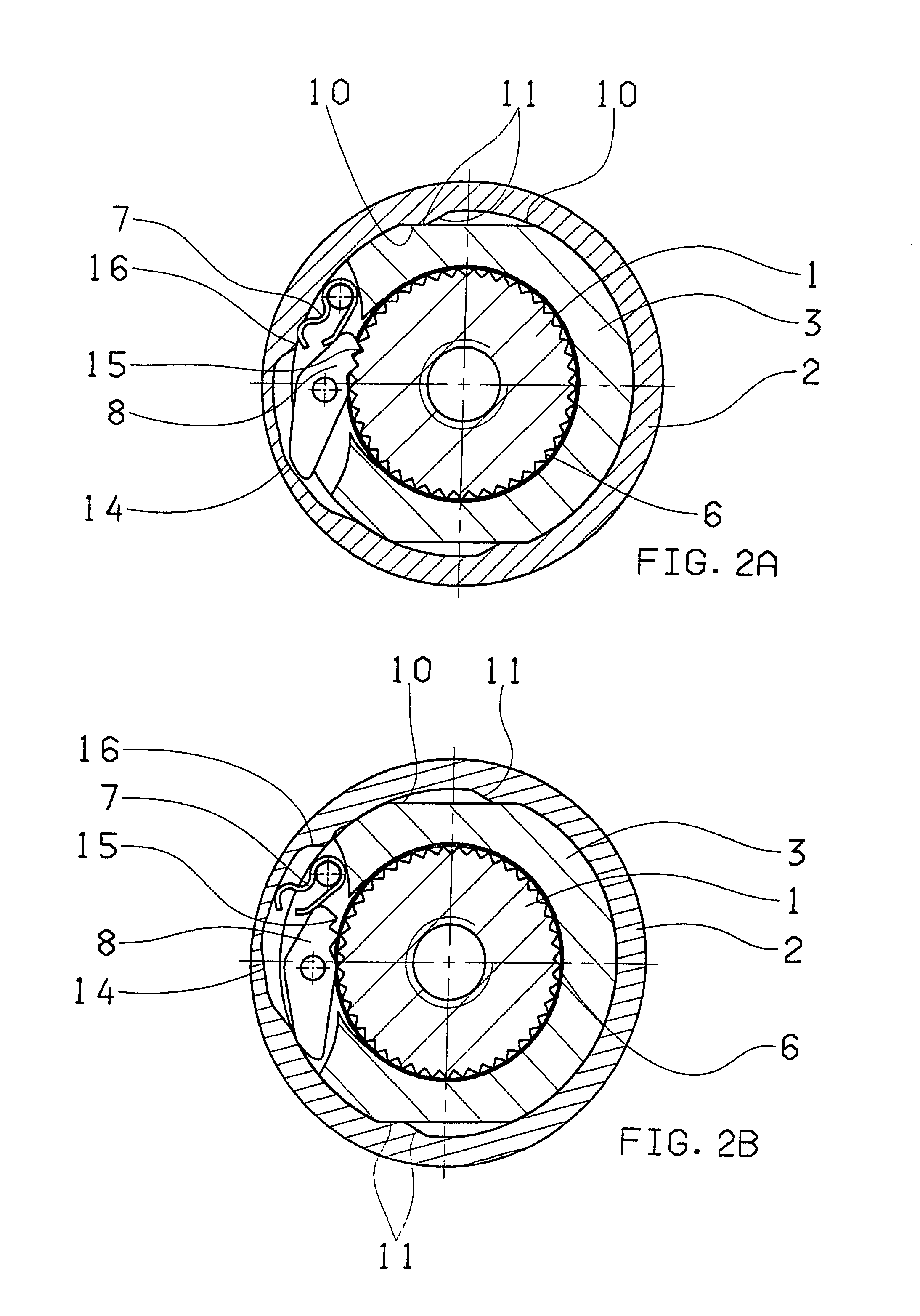
[0047]In the drawings FIG. 1 shows a self-tightening drill chuck comprising a chuck body 1 and a tightening sleeve 2 that can rotate coaxially to chuck body 1 and that is axially supported on a jaw holder 3 mounted on chuck body 1. Holding jaws 4 are guided in guide slots in a jaw holder 3 and can be moved for tightening and loosening by a relative rotation between the chuck body 1 and the tightening sleeve 2 with the jaw holder 3. The drill chuck furthermore comprises a locking device 9 having a ring of gear teeth 6 coaxial to the chuck axis 5 on the one hand and having a detent pawl 8 that is mounted on the jaw holder 3 and engages under the force of a spring 7 into the ring of gear teeth 6 on the other hand in order to lock the chuck body 1 and detent pawl 8 against relative rotation in the loosening direction of the holding jaws 4 when the detent pawl 8 is engaged in the ring of gear teeth 6 but the locking device 9 does not prevent rotation in the tightening direction. FIG. 1 s...


PUM


Abstract

The invention relates to a clamping drill chuck including a chuck body (1), a clamping cone (2) that can be rotated coaxially in relation to the chuck body (1) and is axially supported on a jaw holder (3) mounted on the chuck body (1) and in which clamping jaws (4) are guided in guiding slits, said clamping jaws being adjustable, by means of the jaw holder (3), for the clamping and releasing action by a relative rotation between the chuck body (1) and the clamping cone (2). The drill chuck also includes a locking device (9) provided with a toothed ring (6) which is coaxial to the chick axle (5), in addition to a latch mechanism (8) which is mounted on the jaw holder (3) and engages in the toothed ring (6) when subjected to the force of a spring (7).

Description

CROSS REFERENCE TO RELATED APPLICATIONS[0001]This application is the US national phase of PCT application PCT / DE2006 / 000297, filed 18 Feb. 2006, published 26 Oct. 2006 as WO 2006 / 111114, and claiming the priority of German patent application 102005018392.1 itself filed 20 Apr. 2005 and European patent application 05021864.3 itself filed 7 Oct. 2005, whose entire disclosures are herewith incorporated by reference.FIELD OF THE INVENTION[0002]The invention relates to a self-tightening drill chuck with a chuck body, a tightening sleeve that can rotate coaxially to the chuck body, axially supported on a jaw holder mounted on the chuck body, in which holding jaws guided in guide slots which can be moved for tightening and loosening by a relative rotation between the chuck body and the tightening sleeve with the jaw holder, and with a locking device having a ring of gear teeth coaxial to the chuck axis on the one hand and having a detent pawl that is mounted on the jaw holder and engages u...

Claims


Application Information

Patent Timeline
IPC IPC(8): B23B31/16
CPCB23B31/123B23B31/1253B23B2231/38Y10S279/902Y10T279/32Y10T279/17615Y10T279/20Y10T279/1926
Inventor MACK, HANS-DIETER
Owner ROHM GMBH & CO KG
Why Eureka
Try Eureka