Ink storage container

a technology of storage containers and cylinders, applied in printing and other directions, can solve the problems of unstable air exchange function of valve elements, deterioration of liquid repellent function of liquid repellent agents, and variation of valve elements, so as to achieve stable maintenance, effective use, and stable maintenance over a long period of time

Inactive Publication Date: 2011-12-06
JIT
View PDF17 Cites 4 Cited by
  • Summary
  • Abstract
  • Description
  • Claims
  • Application Information

AI Technical Summary

Benefits of technology

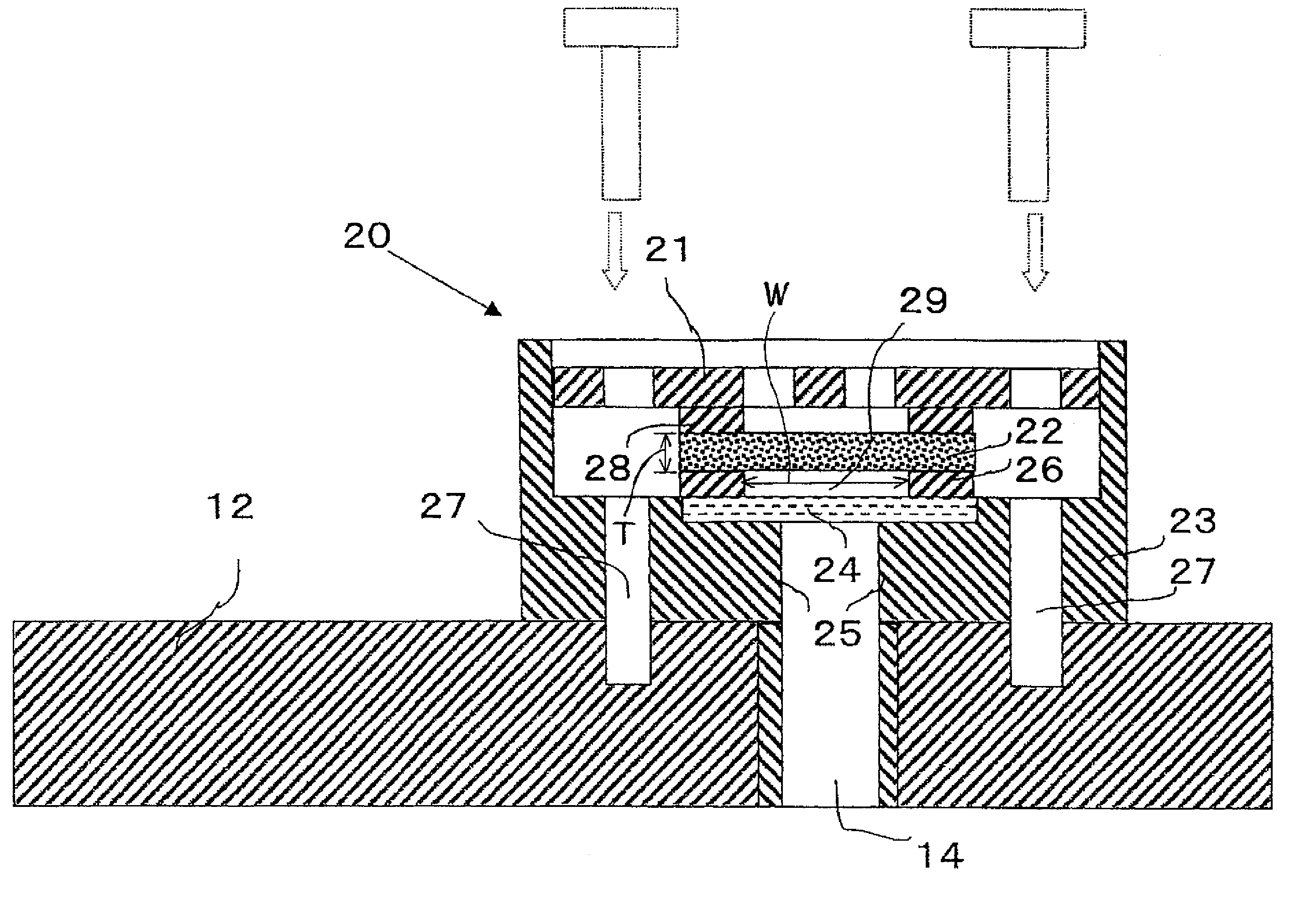
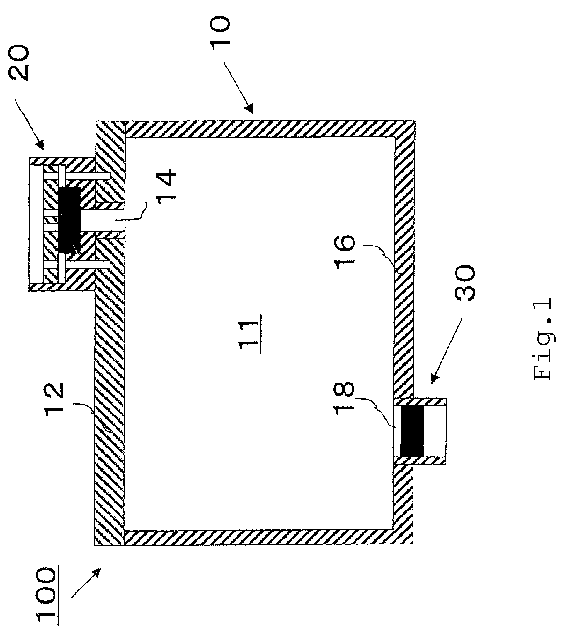
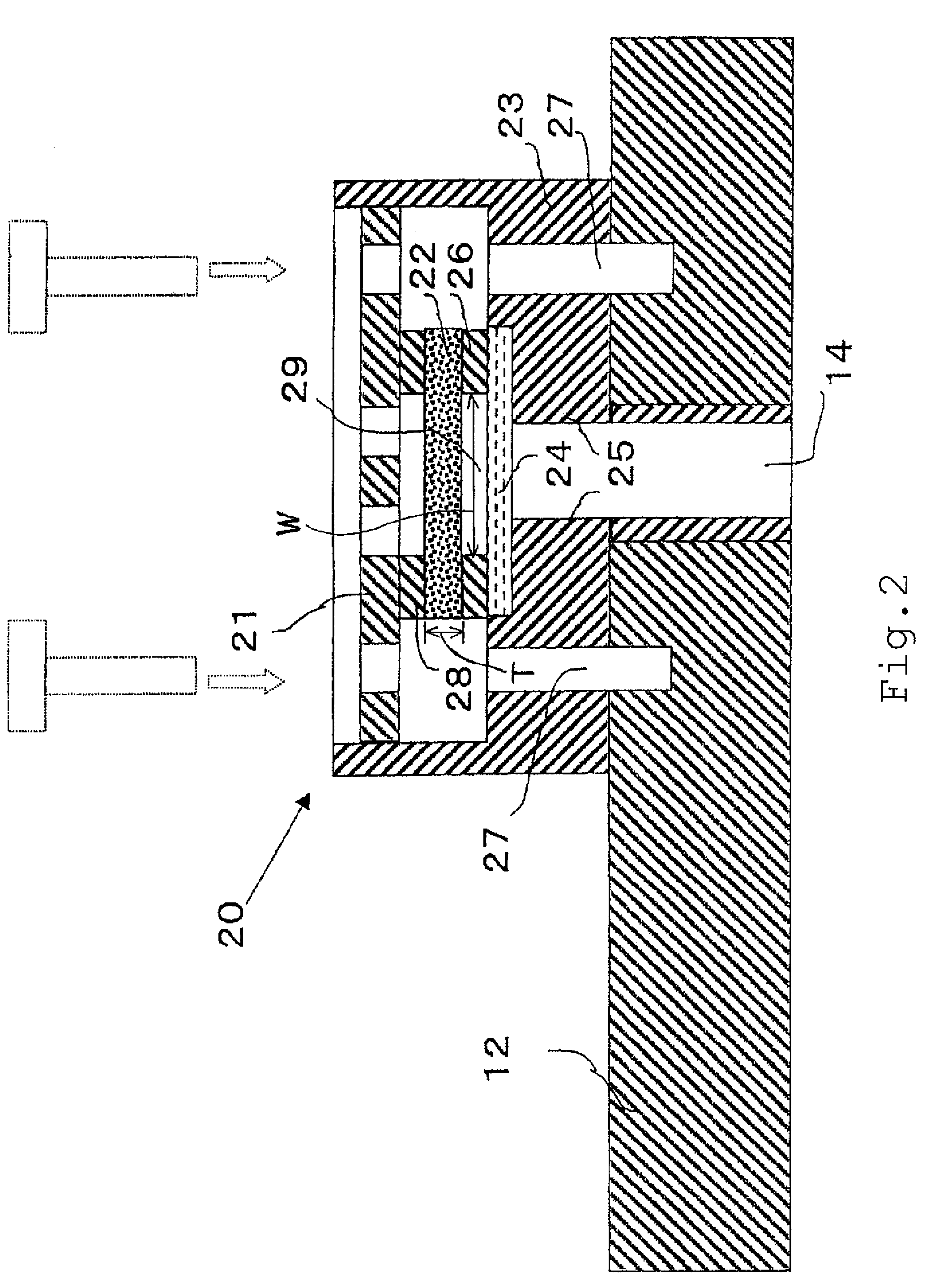
The present invention has been made to solve the above problems, and the utilization efficiency of the ink storage space of an ink storage container is maximized. Accordingly, it is a main object of the invention to provide an ink storage container in which the ink is reliably prevented from adhering to or coming into contact with a valve element. In this ink storage container, the valve element is incorporated in the ink storage container so as not to be influenced by heat during the assembling process of the valve element, to prevent the ventilation control function (air flow control function) of the valve element from deteriorating. Accordingly, the controllability of ventilation through the valve element can be maintained and improved, and furthermore, the ejection of the ink can be suitably and reliably controlled over a range of from a small pressure change to a large pressure change.
In the present invention, the ink is prevented from interfering with the ventilation control of the valve element. Therefore, the air flow control function can be stably maintained, and the ejection of the ink can be suitably controlled over a range of from a small pressure change to a large pressure change. In addition, the ink storage container can be produced at low cost.

Problems solved by technology

Moreover, if the valve element itself is coated with a liquid repellent agent, the air exchange function of the valve element may become unstable, and the function of the valve element may vary with time.
In addition, the liquid repellent function of the liquid repellent agent may deteriorate due to the elastic deformation of the valve element.

Method used


Image

  • Ink storage container
  • Ink storage container
  • Ink storage container

Examples


experimental examples

The ink storage containers described in the first and third embodiments were provided. In the ink storage container of the third embodiment, the diameter of the ink absorbing body 20B2 was set to 5 mm, and the vertical length was set to 30 mm. Ink ejection experiments were performed using an ink-jet printer, and the results obtained are shown in FIG. 24. The results for the ink storage container of the first embodiment are shown by line A, and the results for the ink storage container of the third embodiment are shown by line B. The vertical axis of the graph represents the negative pressure (mmH2O) in the container, and the horizontal axis represents the time course (minutes) of the ink ejection experiment.

For the ink storage container of the first embodiment that is provided only with the air flow control unit, the negative pressure reached −20 to −40 mmH2O as shown by line A. Moreover, the level of the negative pressure is relatively stable. Therefore, it is clear that the ink-je...


PUM


Abstract

An ink storage container having a simply configured ink exchange function is provided, whereby the amount of stored ink is increased. An air flow control unit for controlling the flow of air between the inside and outside is disposed in an ink storage unit for storing ink. The air flow control unit includes: a valve element that is formed of an interconnected porous material and allows air to be exchanged between the inside and outside of the ink storage unit according to positive and negative changes in the internal pressure of the ink storage unit; and a liquid repellent membrane that has air permeability and liquid repellency and is disposed on an ink side of the valve element.

Description

Cross Reference to Related Application:This application claims the benefit of Japanese Patent Application No. 2007-294998, filed on Nov. 14, 2007, Japanese Patent Application No. 2008-080402, filed on Mar. 26, 2008 and Japanese Patent Application No. 2008-184073, filed on Jul. 15, 2008, the disclosures of which Applications are incorporated by reference herein.BACKGROUND OF THE INVENTION1. Field of the InventionThe present invention relates to an ink storage container.2. Description of the Related ArtExamples of the ink storage container include ink tanks for writing instruments and ink cartridges (tanks) for ink-jet printers. Such ink tanks have a mechanism for introducing outside air to the tanks according to the amount of ink consumed for writing and printing characters and images so that the consumption of the ink is not adversely affected by a change in pressure inside the tanks. Examples of such a mechanism include a mechanism including a simple hole formed as an inlet of outs...

Claims


Application Information

Patent Timeline
Patent Type & Authority Patents(United States)
IPC IPC(8): B41J2/175B41J2/19
CPCB41J2/17513B41J2/17553B41J2/17556B41J2/17596
Inventor KAWASAKI, MASAYUKIMATSUO, TAKEHIKOWATANABE, KIMIOMURAMATSU, HIROSHI
Owner JIT
Why Eureka
Try Eureka