Bone marrow harvesting drill

a bone marrow and drill bit technology, applied in the field of bone marrow harvesting drill bit, can solve the problems of high risk of causing gvhd (graft versus host disease), insufficient quantity of bone marrow, and conventional bone marrow puncture needles, etc., to achieve quick harvesting of bone marrow and reduce cutting resistance

Inactive Publication Date: 2011-12-06
JIMRO +1
View PDF18 Cites 7 Cited by
  • Summary
  • Abstract
  • Description
  • Claims
  • Application Information

AI Technical Summary

Benefits of technology

[0014]According to the bone marrow harvesting drill of the invention, a bone is cut with the cutting edge formed at the tip of the inner needle and the cutting edge formed at the tip edge of the tubular mantle. Bone scraps produced by the cutting edge at the tip of the inner needle are discharged from the groove at the tip of the inner needle into the helical groove formed on the peripheral surface of the tubular mantle. Bone scraps produced by the cutting edge of the tubular mantle are also discharged from the helical groove. Thus, the drill of the present invention reduces the cutting resistance due to the clogging of the helical groove by bone scraps, thereby enabling the quick harvest of bone marrow.

Problems solved by technology

In this method, however, since the quantity of bone marrow harvested from one site of a bone is as small as several ml, collecting a sufficient quantity of bone marrow requires a number of sites to be punctured.
Consequently, the method, when used in allogeneic bone marrow transplantation, carries a high risk of causing GVHD (Graft versus Host Disease), which necessitates immunosuppression.
However, the bone marrow puncture needle that is conventionally employed, which is constructed to be inserted into a bone manually by holding a handle, is not suitable for application to the bone marrow perfusion method from the viewpoint of the puncture rate and other factors.
However, the viscosity of collagen, etc., contained in bone tissue resists the discharge of the bone scraps, thus limiting the reduction in the drilling time.

Method used


Image

  • Bone marrow harvesting drill
  • Bone marrow harvesting drill
  • Bone marrow harvesting drill

Examples


Embodiment Construction

[0030]Preferable embodiments of the bone marrow harvesting drill according to the invention will be described below with reference to FIGS. 1 to 15.

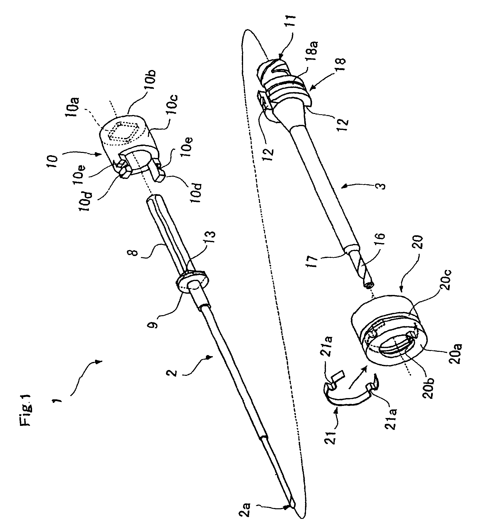
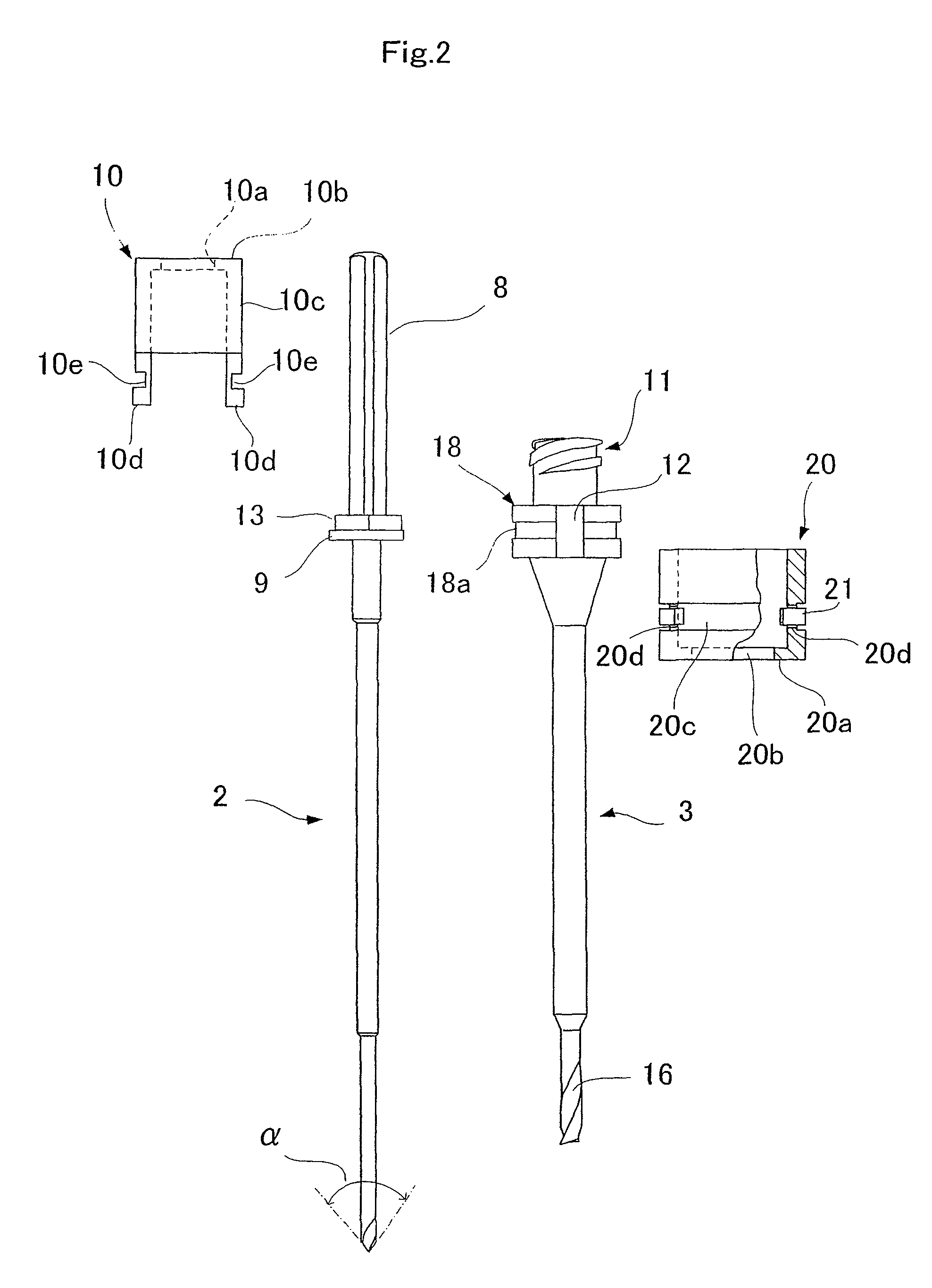
[0031]FIG. 1 is an exploded perspective view showing a first embodiment of the bone marrow harvesting drill, and FIG. 2 is an exploded plan view. As shown in FIG. 1, a bone marrow harvesting drill 1 includes an inner needle 2 and a tubular mantle 3 into which the inner needle 2 can be inserted.

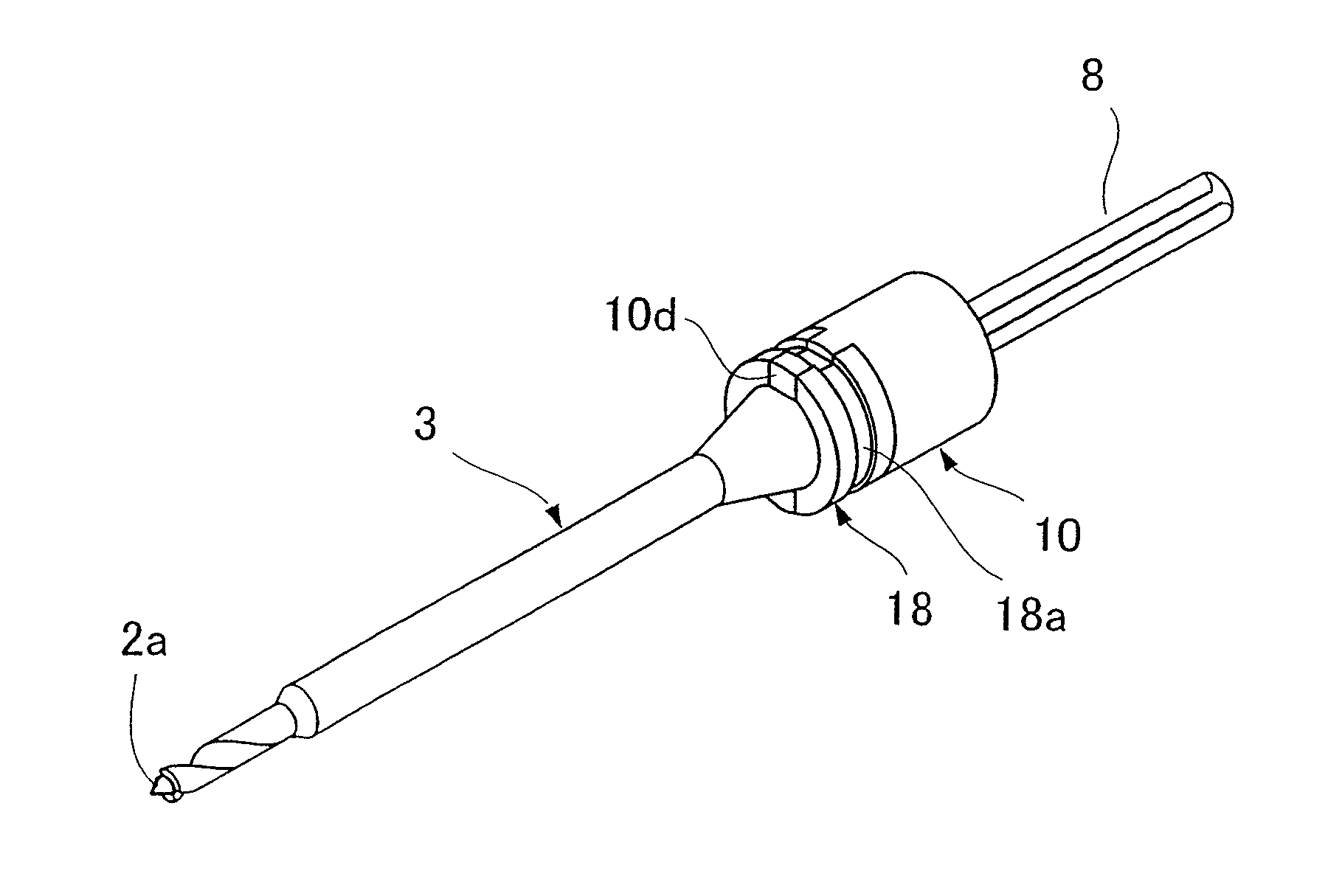
[0032]The inner needle 2 is, as enlarged in FIGS. 3 and 4, provided at its tip with a cutting edge 4 and a groove 5 for discharging bone scraps produced by the cutting edge 4. The cutting edge 4 is an intersection line of a flank 6 and a rake face 7. The tip 2a of the inner needle 2 preferably has a given tip angle α (FIG. 2).

[0033]The inner needle 2 is provided at its rear end with a shank 8 to be held in a drill chuck. The inner needle 2 is further provided with a circular flange 9 at the base of the shank 8. When the inner needle 2 is inserted i...


PUM


Abstract

The bone marrow harvesting drill of the invention includes an inner needle having a cutting edge at the tip thereof; a tubular mantle that receives the inner needle thereinto so that the inner needle and the tubular mantle are detachably attached; and a lock mechanism that prevents the axial rotation of the tubular mantle and the inner needle relative to each other; the inner needle having a groove formed at the tip thereof projecting from the tubular mantle for discharging bone scraps produced by the cutting edge at the tip of the inner needle; and the tubular mantle having a cutting edge formed at the tip edge thereof and a helical groove extending from the tip edge to at least part of the peripheral surface of the tubular mantle so as to be flush with the groove of the inner needle.

Description

TECHNICAL FIELD[0001]The present invention relates to a bone marrow harvesting drill to be used for, for example, drilling a bone to harvest bone marrow.BACKGROUND ART[0002]Bone marrow has generally been harvested using a bone marrow puncture needle to manually puncture the ilium. This kind of bone marrow puncture needle is constructed in such a manner as to insert and fit an inner needle into a tubular mantle while allowing the tip of the inner needle to project from the mantle. The bone marrow puncture needle, which is equipped with a handle in the mantle, percutaneously punctures the ilium, and once the tip of the needle reaches bone marrow, the inner needle alone is drawn out and the mantle remains in contact with the bone marrow for subsequent use.[0003]As a method for harvesting bone marrow using this bone marrow puncture needle, typically, an aspiration method is employed. The aspiration method is such that the mantle of the bone marrow puncture needle is connected to a syrin...

Claims


Application Information

Patent Timeline
Patent Type & Authority Patents(United States)
IPC IPC(8): A61B10/02
CPCA61B10/025A61B17/1617A61B17/1635A61B2010/0258A61B17/17A61B17/1633A61B17/16
Inventor IKEHARA, SUSUMUSHIRAFUJI, HIROSHINAKAMURA, SHUJISHIMODA, NOBUOSADO, KATSUYUKI
Owner JIMRO
Why Eureka
Try Eureka