Inverted embolic protection filter

a technology of embolism and filter, applied in the field of embolic protection devices, can solve the problems of diminishing the perfusion rate of blood through the filter over time, and achieve the effect of improving the blood perfusion characteristics

Inactive Publication Date: 2011-12-06
BOSTON SCI SCIMED INC
View PDF258 Cites 83 Cited by
  • Summary
  • Abstract
  • Description
  • Claims
  • Application Information

AI Technical Summary

Problems solved by technology

As a result of the buildup of embolic debris within the filter, the perfusion of blood through the filter diminishes over time.

Method used


Image

  • Inverted embolic protection filter
  • Inverted embolic protection filter

Examples


Embodiment Construction

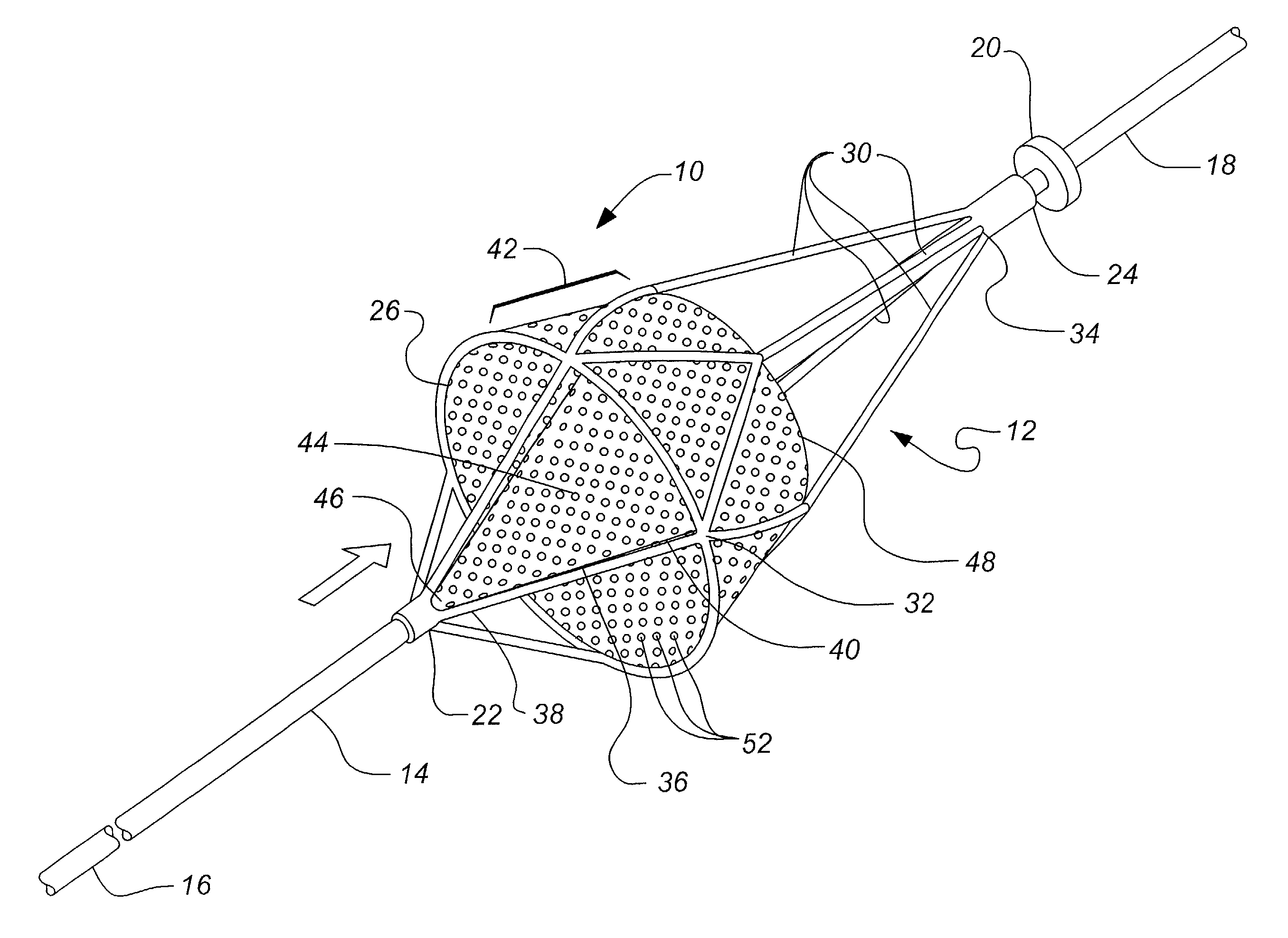
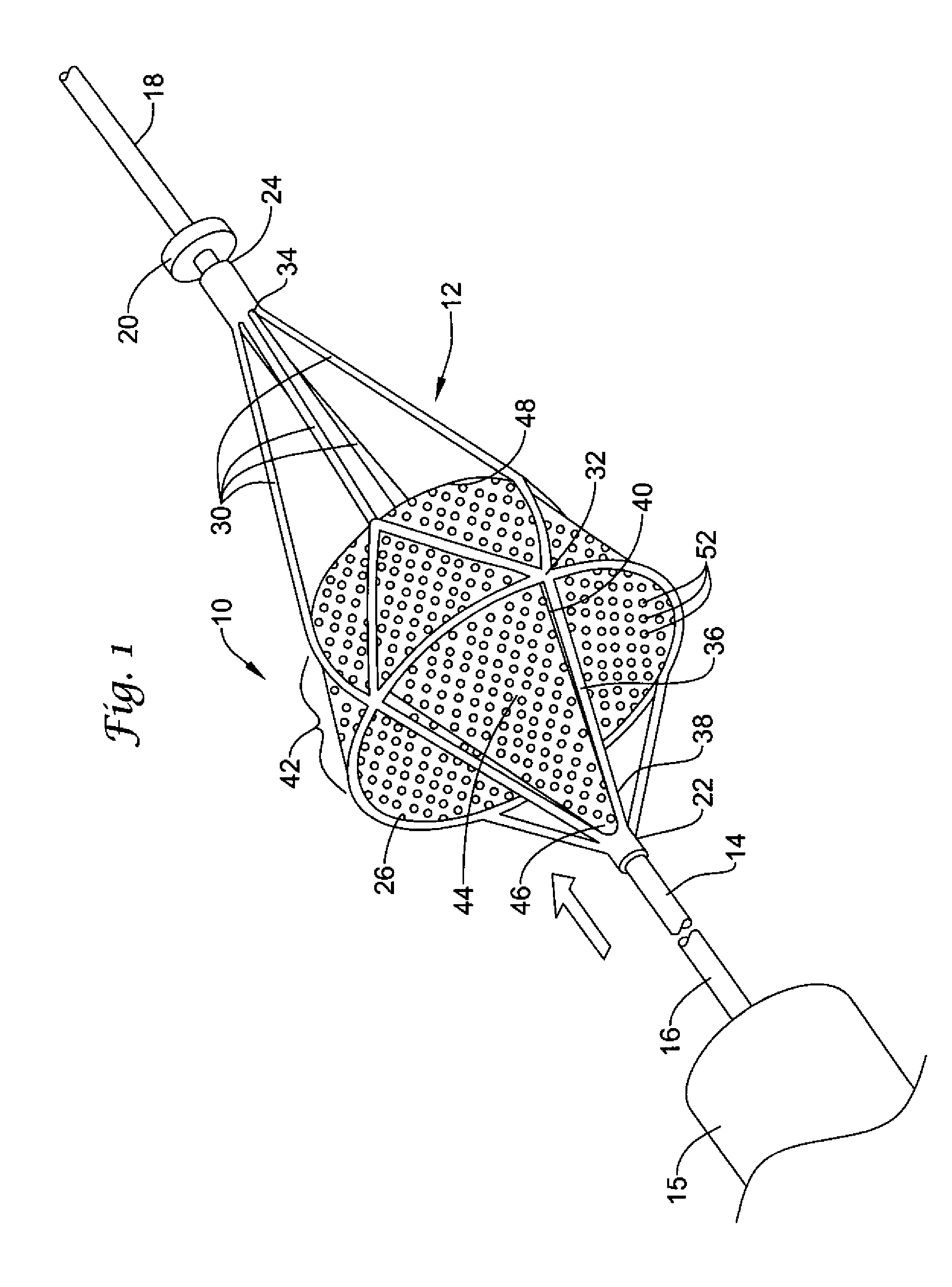
[0007]FIG. 1 is a perspective view of an inverted embolic protection filter 10 in accordance with an exemplary embodiment of the present invention. As shown in FIG. 1, embolic protection filter 10 includes a filter frame 12 disposed about a guidewire 14. Guidewire 14 has a proximal end 16, a distal end 18, and a distal stop 20. Filter frame 12 comprises a first tubular member 22 disposable about guidewire 14, and a second tubular member 24 disposable about guidewire 14 distal the first tubular member 22.

[0008]In the exemplary embodiment illustrated in FIG. 1, embolic protection filter 10 is slidably and rotationally disposed about guidewire 14. The first tubular member 22 and second tubular member 24 each define a lumen (not shown) having an inner diameter that is slightly larger than the outer diameter of the guidewire 14, thereby permitting the embolic protection filter 10 to freely slide and rotate about the guidewire 14. An optional coating may be applied to the inner diameter o...


PUM


Abstract

An embolic protection filter having an inverted membrane with improved blood perfusion characteristics is disclosed. An embolic protection filter in accordance with the present invention comprises a filter frame disposable about a guidewire, a support hoop coupled to a plurality of expandable struts, and an inverted membrane for filtering embolic debris. The inverted membrane has a tapered proximal section and an enlarged diameter distal section. Features of the present invention permit the perfusion of blood through the filter irrespective of embolic debris entrained therein.

Description

FIELD OF THE INVENTION[0001]The present invention relates generally to the field of embolic protection devices. More specifically, the present invention pertains to embolic protection filters having improved blood perfusion characteristics.BACKGROUND OF THE INVENTION[0002]Intravascular filters such as embolic protection filters are generally placed within a body lumen, such as an artery or vein, downstream of a therapeutic site to filter embolic debris from the blood stream. Examples of therapeutic procedures employing such filters include angioplasty, atherectomy, thrombectomy and stent placement. In a typical procedure, a guidewire is transluminally inserted into the patient and placed across the site of the lesion. An embolic protection filter is then advanced along the guidewire and placed distal the lesion. A therapeutic device such as a dilatation or atherectomy catheter is then advanced along the guidewire and placed proximal the therapeutic site to perform the procedure. The...

Claims


Application Information

Patent Timeline
Patent Type & Authority Patents(United States)
IPC IPC(8): A61M29/00A61B17/00A61F2/01A61M1/34
CPCA61F2/013A61F2002/015A61F2002/018A61F2230/0006A61F2230/0067A61F2/0108
Inventor BROOME, THOMAS E.
Owner BOSTON SCI SCIMED INC
Why Eureka
Try Eureka