Reactive sputtering method

a sputtering method and sputtering technology, applied in the field of bias sputtering method, can solve the problems of low film formation speed of metal compound as compared with the film formation speed of metal compound, low film density, rough film surface, etc., and achieve the effect of minimizing the damage to the film formed

Inactive Publication Date: 2011-12-06
FUJIFILM CORP
View PDF3 Cites 37 Cited by
  • Summary
  • Abstract
  • Description
  • Claims
  • Application Information

AI Technical Summary

Benefits of technology

[0009]The invention relates to a sputtering apparatus for continuous film formation, in which the damage to the film formed is minimized even at a high film formation speed.

Problems solved by technology

In this method, however, in case where the film formation speed greatly differs between metal and metal compound such as Al and Al2O3 and when a metal compound having a sufficient stoichiometric ratio is formed into a film through reactive sputtering, then there may occur a problem in that the film formation speed of the metal compound is relatively low as compared with the film formation speed of the metal alone.
In this method, the film formation speed is high since the film formation is carried for a metal; in this, however, the film formed is re-etched on the substrate, therefore causing a problem in that the film surface may be roughened and the film density may lower.
Accordingly, in this, when the electrons are not discharged on the entire periphery, the electrons may be shifted and the efficiency may worsen.
Therefore, in the method, the discharging must occur in every site on the carousel periphery, and continuous film formation that requires substrate change is impossible.
One reason for lowering most the production speed in film production in a mode of vacuum film formation is that vacuum breaking and degassing into vacuum takes too much time.
However, this apparatus could not evade the above-mentioned prior-art problems.

Method used


Image

  • Reactive sputtering method
  • Reactive sputtering method
  • Reactive sputtering method

Examples


examples

[0096]The invention is described more concretely with reference to the following Examples, in which the material used, its amount and the ratio, the details of the treatment and the treatment process may be suitably modified or changed not overstepping the spirit and the scope of the invention. Accordingly, the invention should not be limited to the Examples mentioned below.

(Formation of Inorganic Film I1)

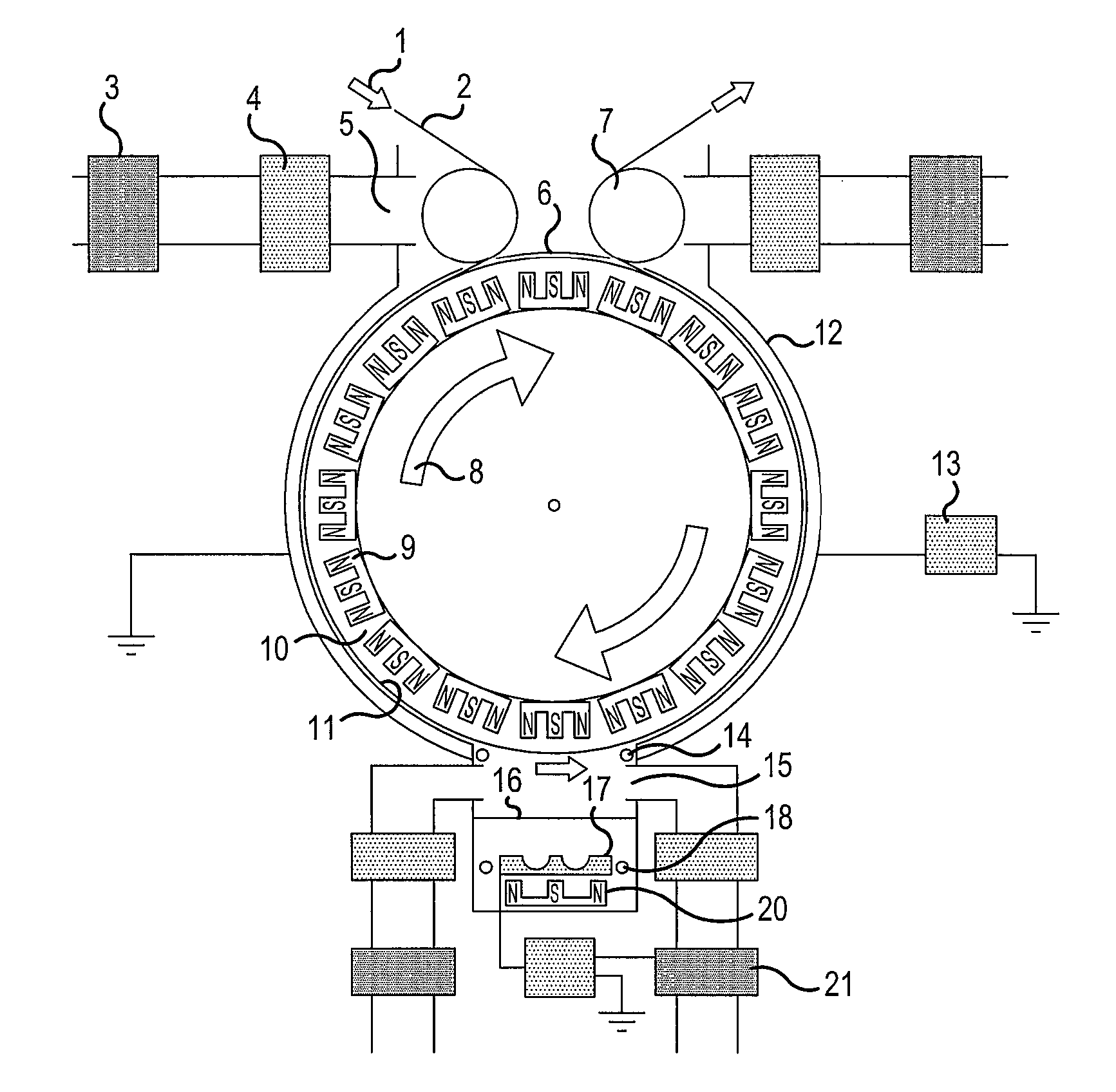
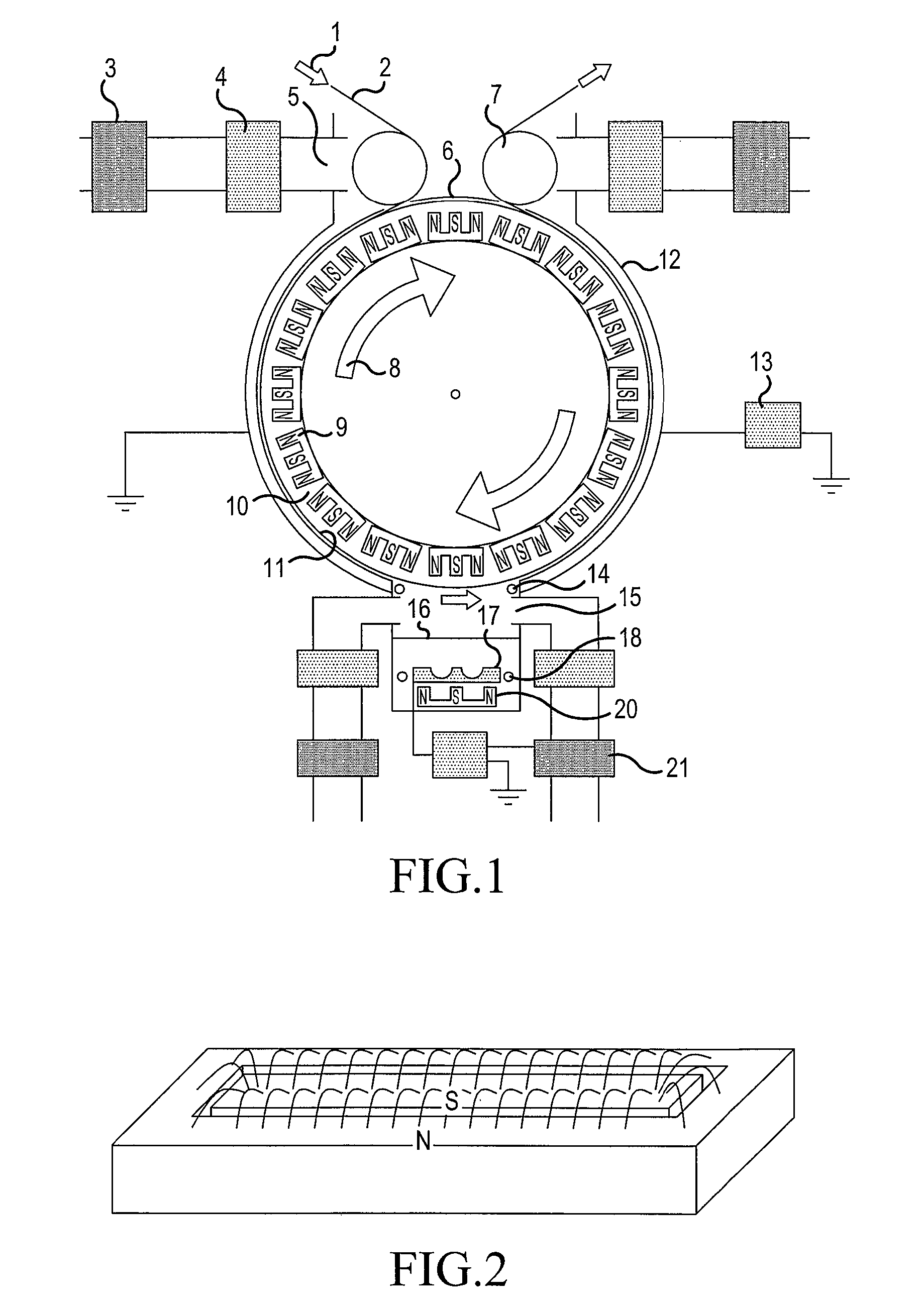
[0097]An apparatus of FIG. 4 was used. Al was used as the target. A process gas Ar was introduced through the introduction port 19 at 2.0 sccm, and a cathode power 1000 W was applied for plasma discharging. With the drum kept cooled and rotated, Al was deposited on a PEN film to be a thickness of 50 nm, thereby forming an inorganic film I1.

(Formation of Inorganic Film I2)

[0098]An apparatus of FIG. 4 was used. Al was used as the target. A process gas Ar was introduced through the introduction port 19 at 2.0 sccm, and a cathode power 1000 W was applied for plasma discharging. In this...


PUM

PropertyMeasurementUnit
pressureaaaaaaaaaa
pore-to-pore distanceaaaaaaaaaa
Tgaaaaaaaaaa

Abstract

A reactive sputtering method for application of a bias voltage to a supporting substrate in formation of a film of a metal compound on the supporting substrate according to a bias sputtering method; wherein a supporting substrate conveyor unit and a cathode that includes a target facing the supporting substrate conveyor unit are provided; the supporting substrate is conveyed between the supporting substrate conveyor unit and the target for formation of a film of a metal compound on the supporting substrate; magnets are provided adjacent to the supporting substrate conveyor unit on a side thereof opposite to that of the supporting substrate, such that a magnetic field is closed and a continuing tunnel part of parallel or nearly parallel arched magnetic force lines forms an oval or a polygon on the supporting substrate, the magnets each having a first magnetic pole of an S pole or an N pole and a second magnetic pole opposite to the first magnetic pole, the second magnetic pole surrounding the first magnetic pole; and in film formation on the supporting substrate, the magnets are rotated inside a drum in an opposite direction to that in which the supporting substrate is conveyed outside of the drum, so as to secure uniform plasma application along the supporting substrate.

Description

TECHNICAL FIELD[0001]The present invention relates to a bias sputtering method for film formation through reactive sputtering with a metal compound, in which a bias is applied to the supporting substrate, and to magnet arrangement on the back of the supporting substrate when a film of a metal compound continuously formed on the supporting substrate.BACKGROUND ART[0002]For sputtering with a target, there is known a method of film formation with a metal compound which comprises introducing a reactive gas followed by reacting the reactive gas with a metal (reactive sputtering method). This method is characterized in that, in general, Al, Si or the like is used as the target, a rare gas such as He or Ar is used as the process gas, and O2, N2 or the like is used as the reactive gas; and that the target is reacted with the reactive gas and, as a result, a metal compound is formed on a substrate.[0003]For high-speed film formation according to conventional reactive sputtering, employed is ...

Claims


Application Information

Patent Timeline
Patent Type & Authority Patents(United States)
IPC IPC(8): C23C14/35C23C14/54C23C14/06C23C14/50
CPCC23C14/0036C23C14/044C23C14/081C23C14/345C23C14/351C23C14/562H01J37/3277H01J37/3405
Inventor TSUKAMOTO, NAOKI
Owner FUJIFILM CORP
Why Eureka
Try Eureka