
Dental light curing device coupled to a light measuring device

a curing device and light curing technology, applied in the direction of optical radiation measurement, instruments, spectrometry/spectrophotometry/monochromators, etc., can solve the problems of design being unable to deliver an exact measurement and detection of the luminous density in the measured region of the light exit surfa

Active Publication Date: 2011-12-06
IVOCLAR VIVADENT AG
View PDF5 Cites 5 Cited by
  • Summary
  • Abstract
  • Description
  • Claims
  • Application Information

AI Technical Summary

Benefits of technology

The invention provides a light measuring device with measurement fields that can detect the illumination intensity of a light source in a simple way. The measurement fields can be distributed in two dimensions or in a matrix. The device can also compensate for obliquity errors and can be used even without exact alignment on the measurement surface. The measurement fields have spectral sensitivity adapted to the emission spectrum of the light source. The device can also have a stop to delimit the movement of the light guiding device. The measurement fields can be designed as sensors in the form of mutually identical photosensors. The device can also have a display device for displaying the illumination intensity and the diameter of the light exit surface of the light guide.

Problems solved by technology

However, with this solution there is the grave disadvantage that fundamentally only the luminous density in the measured region of the light exit surface is detected.
This means that only a lesser fraction in percentage terms of the emitted light power is detected in conjunction with a comparatively large light exit surface, and so erroneous measurements occur to this extent on different sizes of the light exit surfaces.
In particular, even in the case of this solution it is not possible to conduct a distance measurement in which the light curing device is thus merely held over the sensor field in order to determine whether the emitted illumination intensity is still sufficient, because erroneous measurements then always occur in the case of this solution owing to the beam expansion.
On the other hand, this design is not able to deliver an exact measurement result when the light exit surface has a shape deviating from the circular one.

Method used


Image

  • Dental light curing device coupled to a light measuring device
  • Dental light curing device coupled to a light measuring device
  • Dental light curing device coupled to a light measuring device

Examples


Embodiment Construction

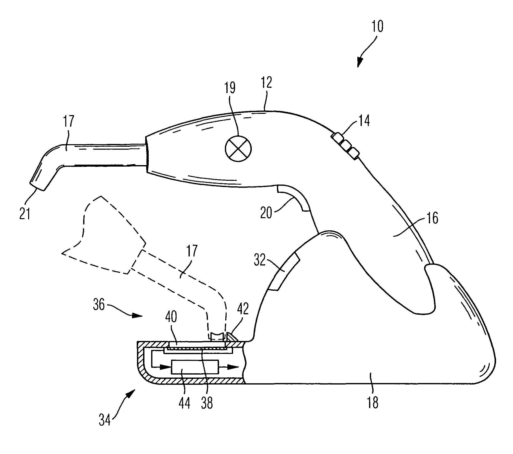
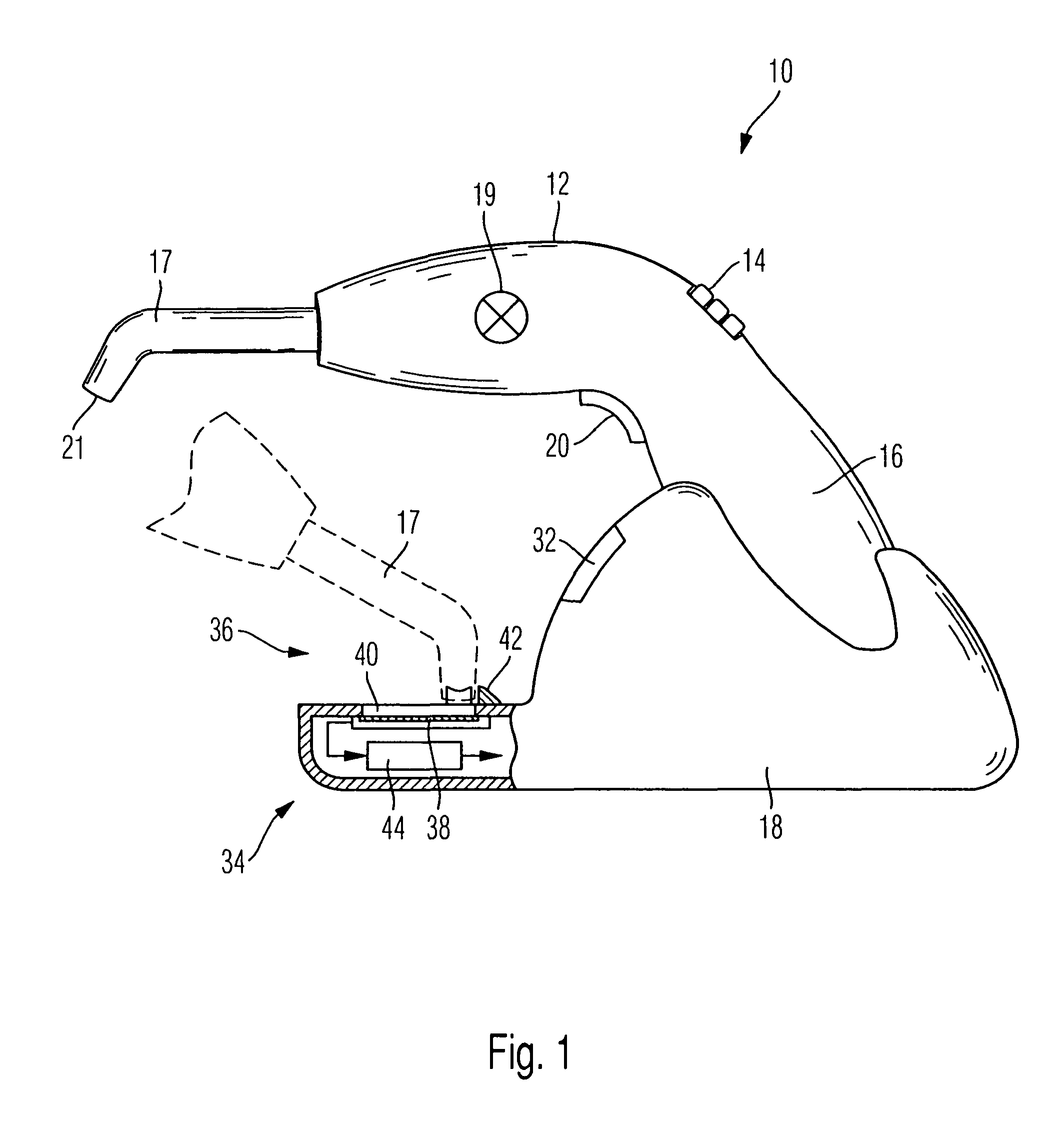
[0037]The light curing device 10 illustrated in FIG. 1 has a housing 12 and a display device 14 that is located on top of the rear side on a pistol grip 16 of the light curing device 10. At the front end of the housing 12, the light curing device has a light guiding device 17 that feeds light from a schematically illustrated light source 19 to a light exit surface 21 at the front end of the light guiding device.

[0038]As an exemplary device that accommodates a light source 19, the light curing device 10 can be put down in a base station 18. In a way known per se, the device has in the pistol grip storage batteries that, when the device is put down in the base station 18, are automatically charged whenever the charge state of the storage batteries so requires. The light curing device can be switched on via a momentary contact switch 20 that is arranged on the inner side of the pistol grip 16 in a way known per se. In the switched-on state of the device, light is emitted by the schemat...


PUM


Abstract

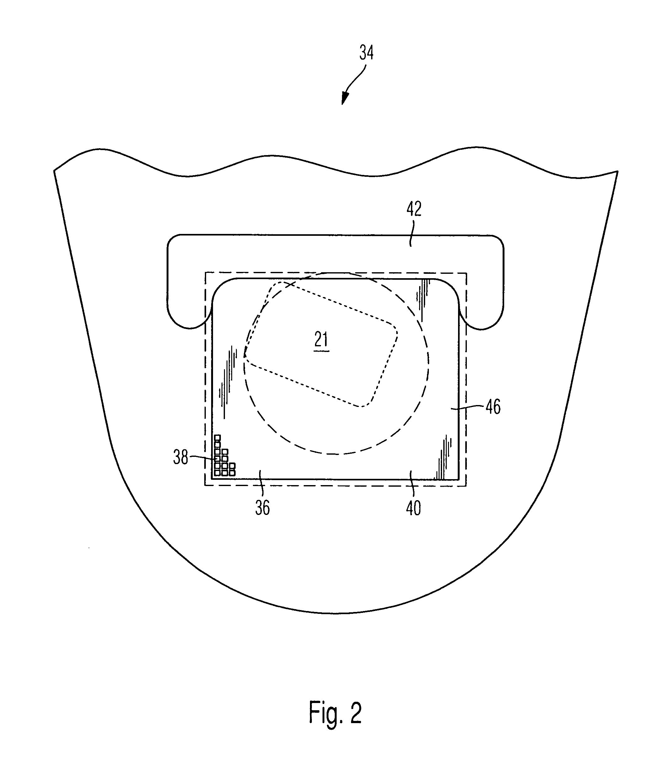
The invention relates to a light measuring device 34, in particular for dental light curing devices, for detecting the illumination intensity of a light source 19, which is arranged, in particular, in the light curing device, to which a light guiding device, in particular, having a light exit surface 21 at its outlet, is connected, the light measuring device 34 having at least four measurement fields 38 distributed in two dimensions.

Description

CROSS-REFERENCE TO RELATED APPLICATIONS[0001]This application claims foreign priority benefits under 35 U.S.C. §119(a)-(d) from German patent application ser. no. P 10 2007 052 643.3 filed Nov. 5, 2007.TECHNICAL FIELD[0002]The invention relates to a light measuring device, in particular for dental light curing devices, and more particularly to such a device which detects the illuminating intensity of a light that exits from the light exit surface of a light guiding device of the light curing device.BACKGROUND OF THE INVENTION[0003]A light measuring device of the type mentioned above is disclosed, for example, in U.S. Pat. No. 5,115,126. In the case of this light measuring device, which is used for testing endoscopes, the light emitted from a light source is fed via a light guiding device to a sensor arrangement, the endoscope there being tested by comparing the output signal of sensors.[0004]It has already been proposed once to implement a sensor that has a smaller diameter than the...

Claims


Application Information

Patent Timeline
Patent Type & Authority Patents(United States)
IPC IPC(8): G01J1/42
CPCG01J1/4228G01J1/4257A61C19/004G01J1/0488G01J2001/4247
Inventor PLANK, WOLFGANGSENN, BRUNO
Owner IVOCLAR VIVADENT AG
Learn More