Time correlation system and method

a time correlation and time correlation technology, applied in the field of detecting and recording lowlevel light signals, can solve problems such as noise or curve distortion

Inactive Publication Date: 2011-12-06
OPTECH VENTURES
View PDF9 Cites 54 Cited by
  • Summary
  • Abstract
  • Description
  • Claims
  • Application Information

AI Technical Summary

Problems solved by technology

Any non-uniformity of the channel width results in a systematic variation of the numbers of photons in the channels, creating noise or curve distortion.

Method used


Image

  • Time correlation system and method
  • Time correlation system and method
  • Time correlation system and method

Examples


Embodiment Construction

[0023]Embodiments of the present invention are more particularly described in the following examples that are intended as illustrative only since numerous modifications and variations therein may be apparent to those skilled in the art. As used in the specification and in the claims, “a,”“an,” and “the” can mean one or more, depending upon the context in which it is used. Several embodiments of the present invention are now described with reference to the figures, in which like numbers indicate like parts throughout the figures.

Time-Correlated Single Photon Counting Systems

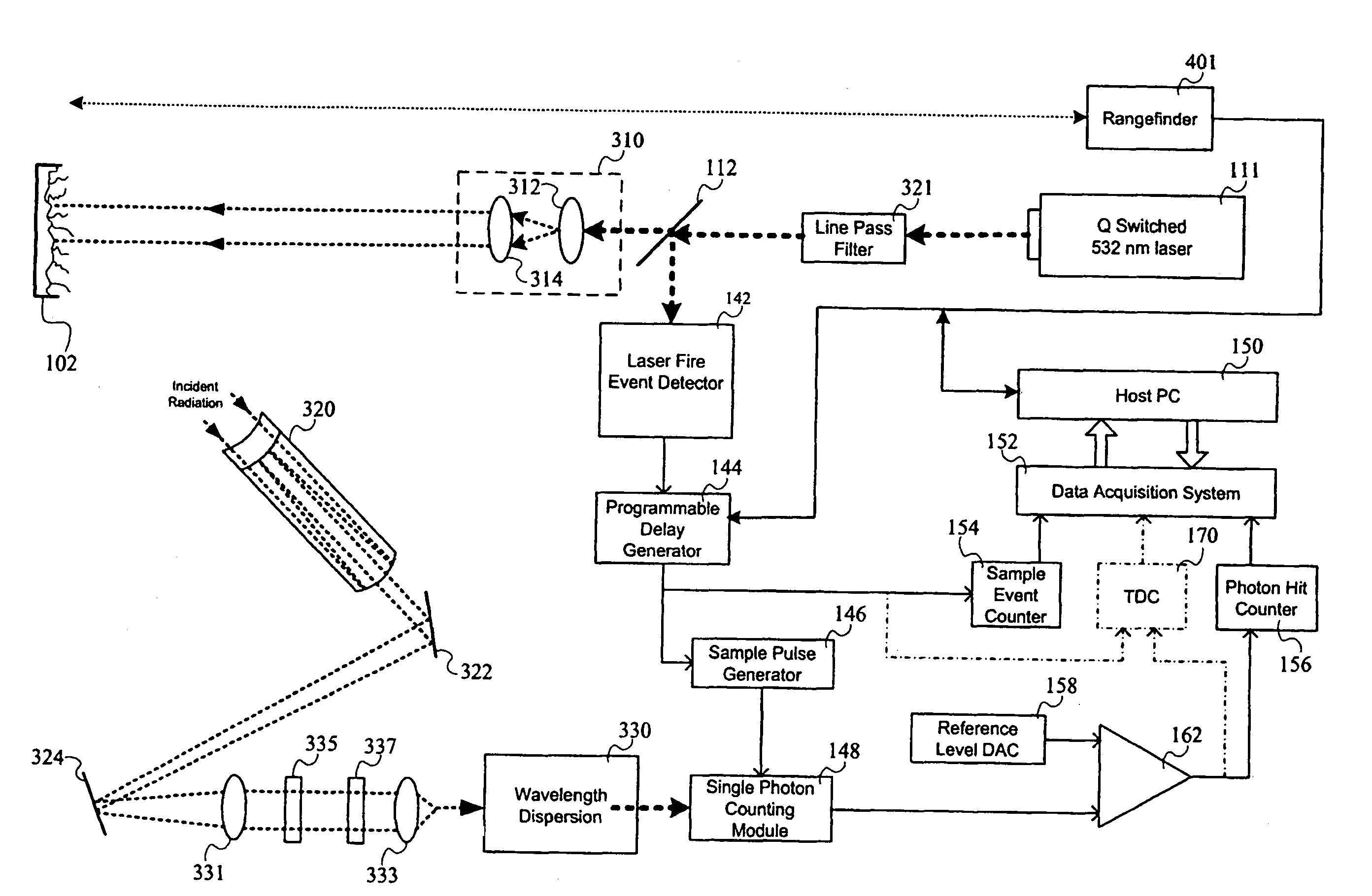
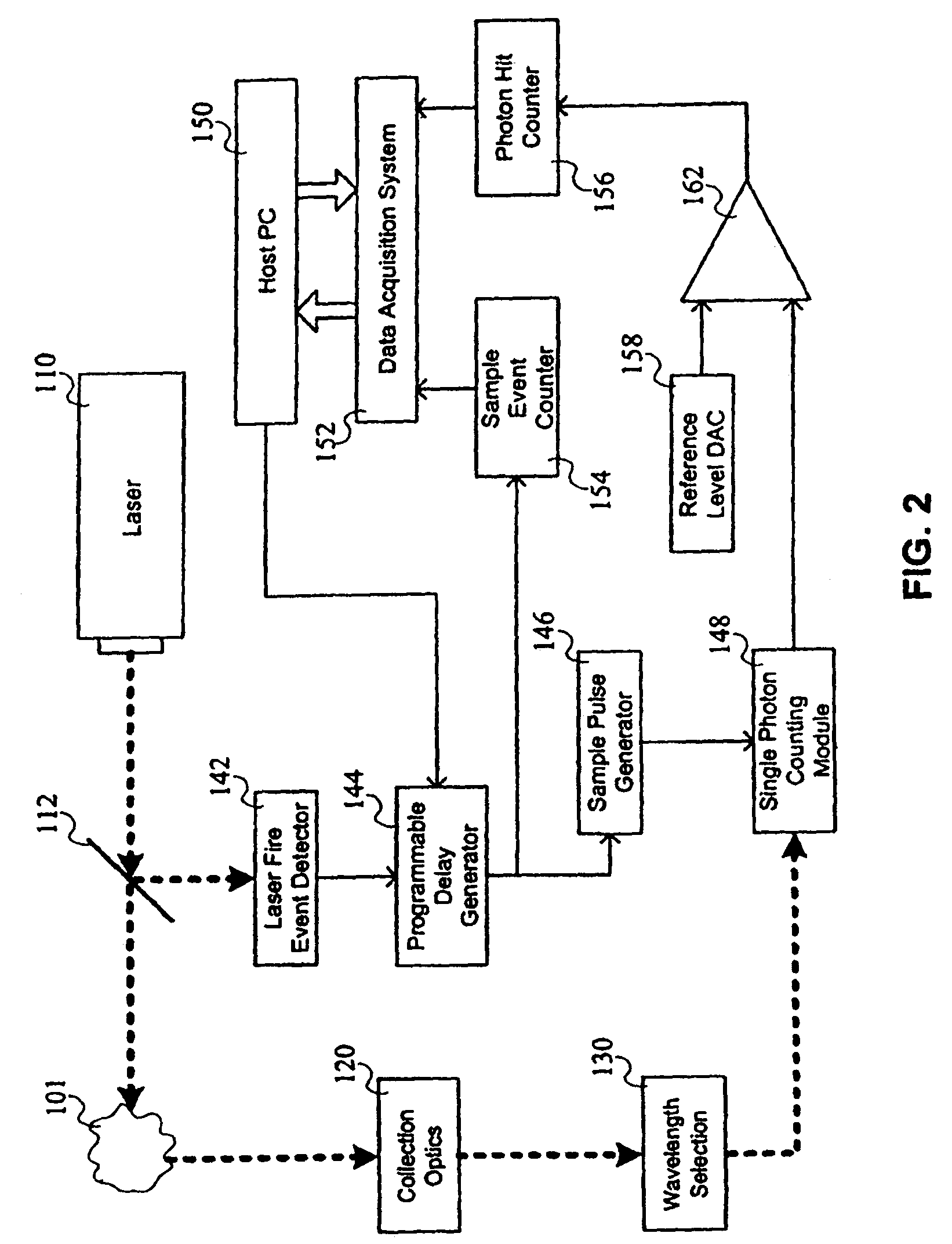
[0024]FIG. 2 depicts a time-correlated single photon counting system according to an embodiment of the present invention. In FIG. 2, a laser 110 fires pulses at a target 101 from which the system collects photons for counting. Additional embodiments of the present invention incorporate such a system for Rayleigh scattering detection or Raman scattering detection. Both embodiments will be described in detail below....


PUM


Abstract

A time correlated single photon counting system having a programmable delay generator triggered by a laser fire event detector. The system may be used for chemical agent detection based on Rayleigh scattering using optical time domain reflectometry techniques. The system may also be used for Raman detection using frequency to time transformations.

Description

RELATED APPLICATIONS[0001]This application claims priority from Provisional Application Ser. No. 60 / 995,146 filed on Sep. 24, 2007 and is a Continuation-In-Part of Utility application Ser. No. 11 / 512,963 filed on Aug. 29, 2006 now abandoned which in turn claims priority from Provisional Application Ser. No. 60 / 712,213 filed on Aug. 29, 2005 which was published on May 24, 2007 as Publication Number 20070114419, the content of all of which are incorporated herein by referenceGOVERNMENT LICENSE RIGHTS[0002]This invention was made with Government support under U.S. Army contract number W911NF-06-C-0039 and TSWG contract number N41756-03-4089. The Government may have certain rights in this patent.FIELD[0003]This disclosure relates to the field of detecting and recording low-level light signals with increased resolution and precision.GENERAL BACKGROUND[0004]Time-correlated single photon counting, or TCSPC, is based on the detection of single photons of a periodic light signal, the measure...

Claims


Application Information

Patent Timeline
Patent Type & Authority Patents(United States)
IPC IPC(8): G01J3/44
CPCG01J3/44G01J3/4412G01N21/65G01N21/7703G01J1/46G01J3/027G01J3/2889G01J2003/1213G01N2021/1793
Inventor BASTIAANS, GLENNHANKINS, STEVECOLE, JERALD ALAN
Owner OPTECH VENTURES
Why Eureka
Try Eureka