Foil stamping machine

a stamping machine and foil technology, applied in the field of foil stamping machines, can solve the problems of low width of stamping foil on the stamping machine, affecting the quality of stamping foil, and affecting the appearance of stamping defects on the item, so as to achieve high reliability and quality of stamping.

Active Publication Date: 2011-12-13
ILLINOIS TOOL WORKS INC
View PDF14 Cites 4 Cited by
  • Summary
  • Abstract
  • Description
  • Claims
  • Application Information

AI Technical Summary

Benefits of technology

[0008]It is these difficulties that the invention is most particularly intended to overcome, by proposing a stamping machine with a fixed or moving stamping punch, allowing a high reliability and quality of stamping to be obtained, even with low stamping foil widths and at high stamping rates.

Problems solved by technology

However, the handling of a stamping foil of low width on a stamping machine is delicate.
Such a variation in the tension of the stamping foil may lead to the appearance of stamping defects on the articles.
The stamping foil thus undergoes strain when it is rewound, which may damage the stamping foil in the case of a low stamping foil width and a high stamping rate.
However, when the stamping foil is to be moved only sequentially, as it is the case for the stamping of individual articles, the use of a rotative control roller driven by a motor and arranged upstream from the embossing gap is not adapted.
In practice, the driving of the stamping foil, notably for a stamping foil of low width, by a rotative roller driven by a motor and arranged upstream from the embossing gap would lead either to the appearance of stamping defects on the articles, due to a too high stamping foil speed causing the stamping foil to accumulate at the stamping member during the stamping, or to the breaking of the stamping foil, due to a too low stamping foil speed causing stamping foil tension peaks.
Indeed, in practice, it would be delicate and even impossible to get a perfect synchronisation of the rotation speed of the control roller relative to the movement of the articles being brought successively opposite the stamping member.

Method used


Image

  • Foil stamping machine
  • Foil stamping machine
  • Foil stamping machine

Examples


first embodiment

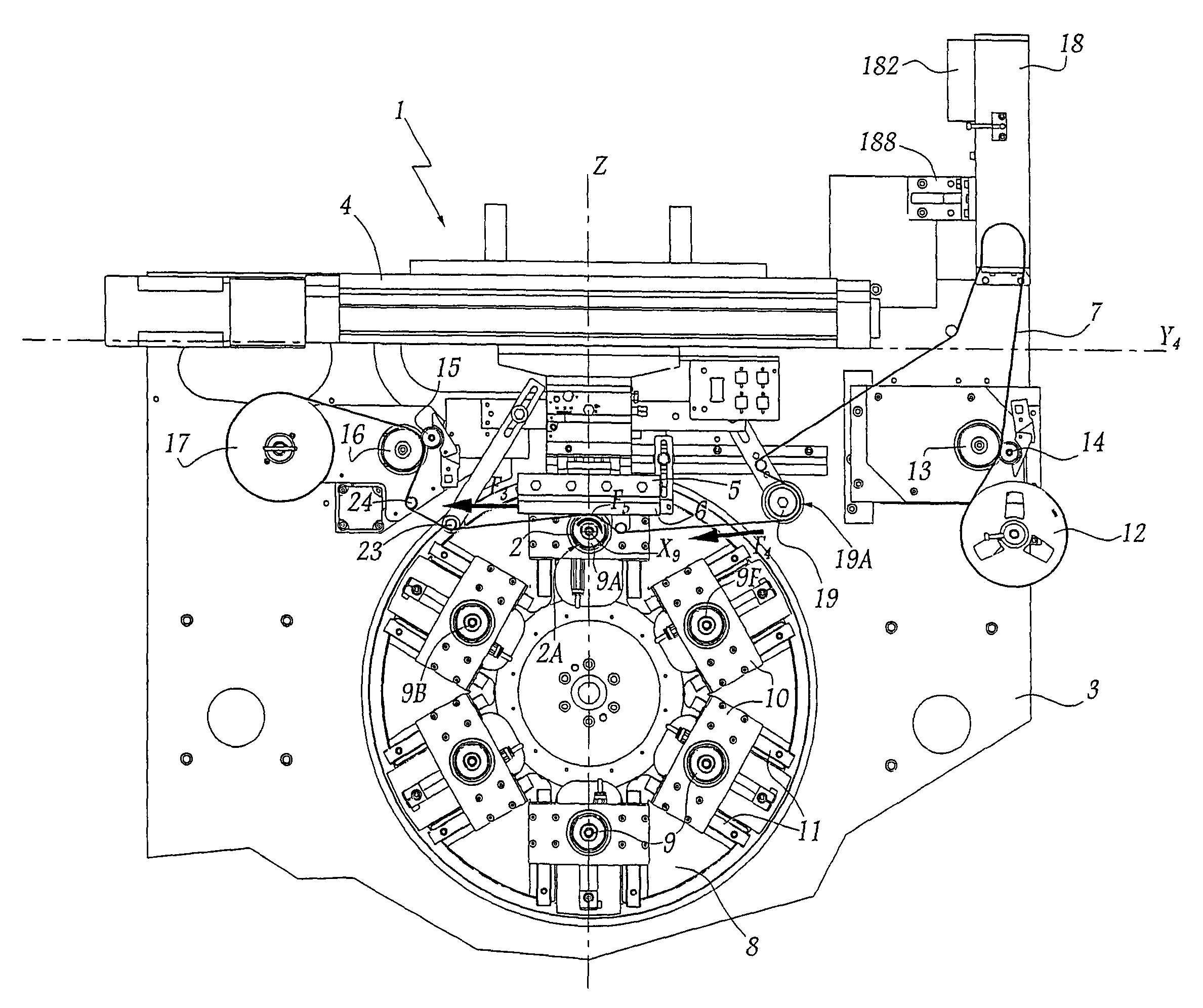
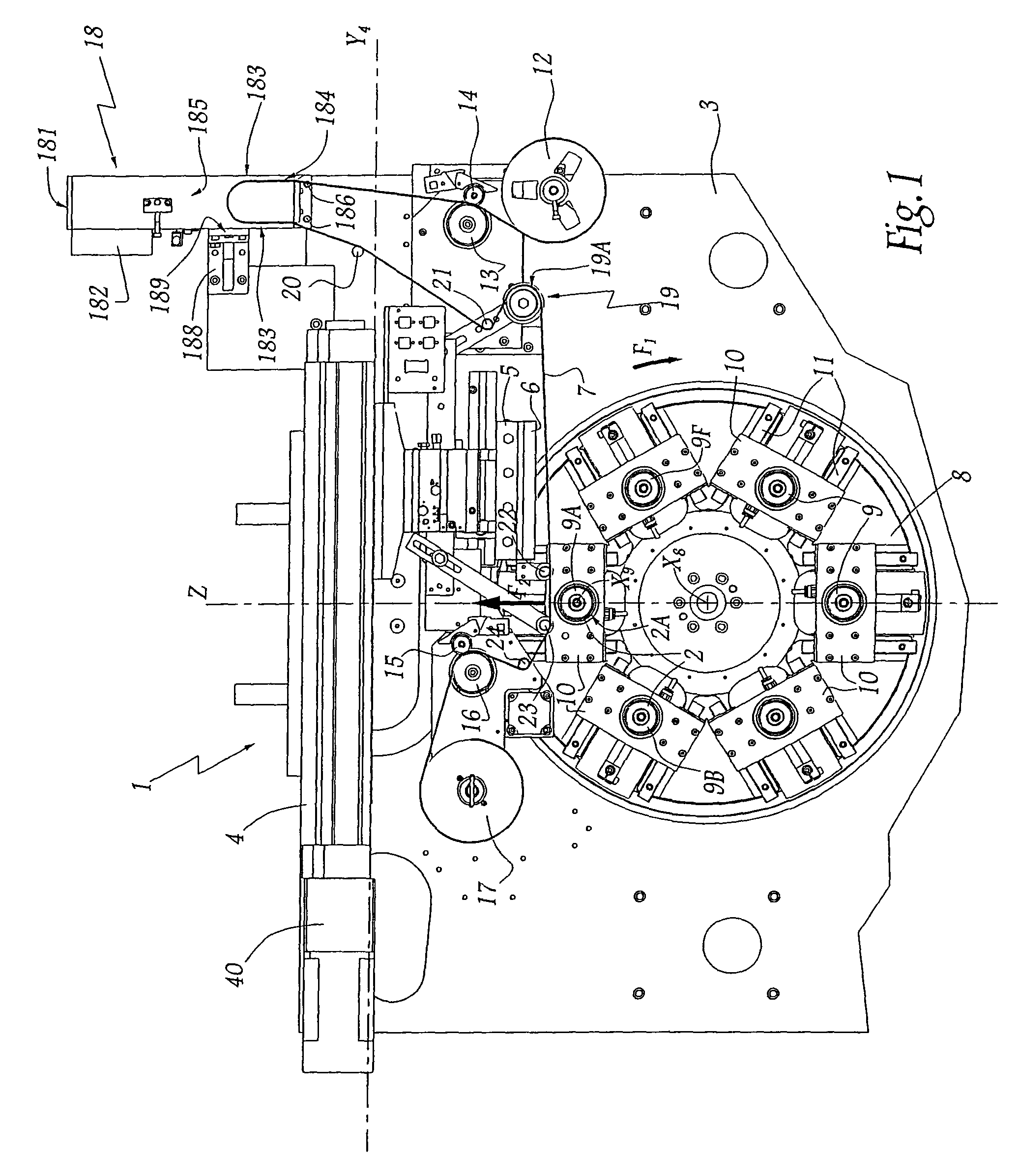
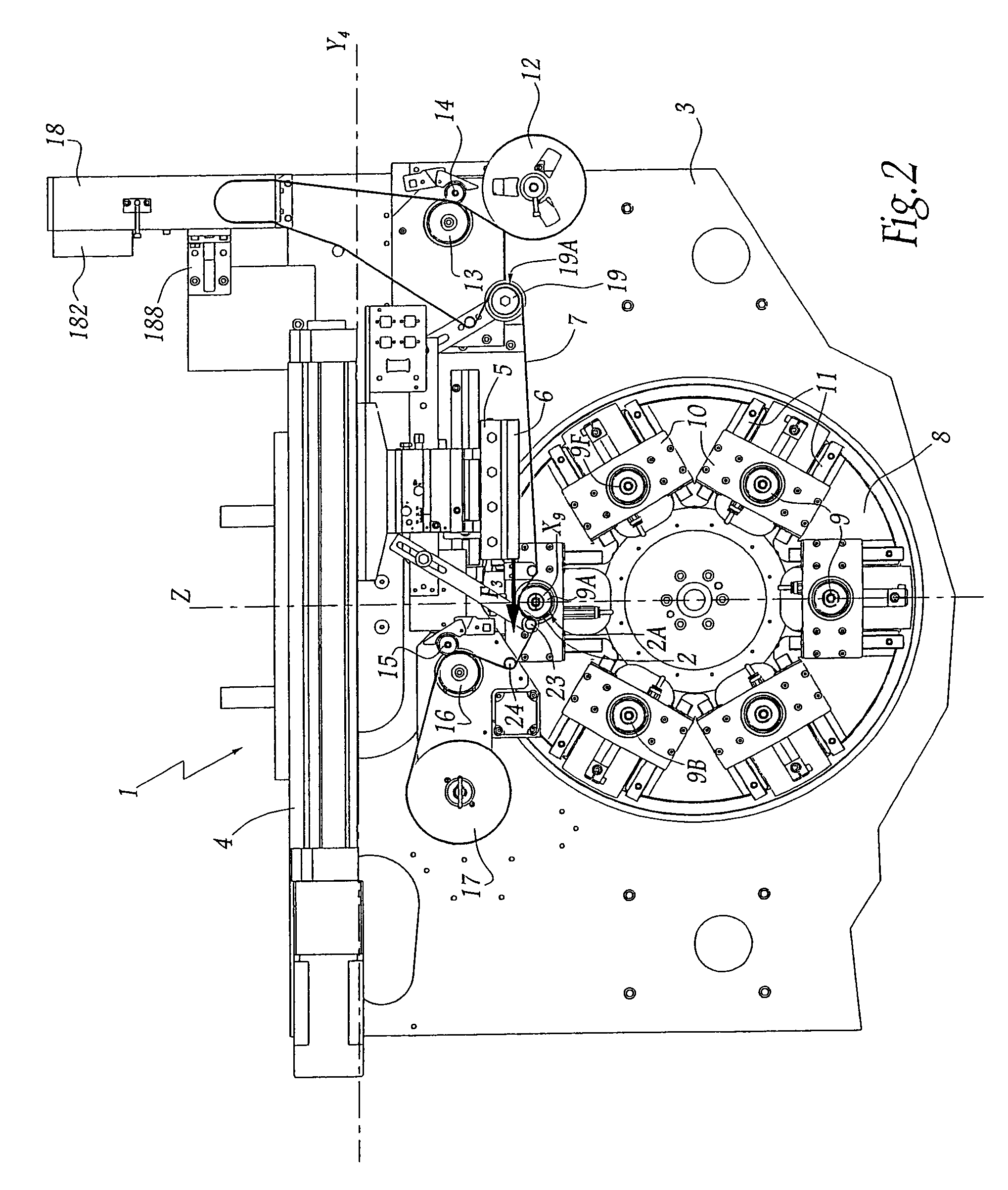
[0053]Upon completion of the steps disclosed above for a stamping sequence for an article 2, the guidance of the stamping foil 7 on the machine 1 according to this first embodiment of the invention allows the stamping of each article 2 to be performed with a high reliability and a high quality of stamping, even for a low width of the stamping foil 7, in particular between 8 mm and 25 mm, and a high stamping rate, for example greater than 3000 articles per hour, in particular greater than 6000 articles per hour, produced by a single stamping head. Indeed, the combination of the suction box 18, located at the output of the motorised unwinding means 12-14, and the braking surface 19A allows a sufficient tension of the stamping foil 7, suitable for the function thereof, to be ensured opposite the punch 6. The tension of the stamping foil 7 is suitable for stamping if it allows upward guidance and lateral guidance of the stamping foil. Thus, the risk of deflection of the stamping foil or...

second embodiment

[0057]A stamping sequence for an article 202 on the machine 201, according to this second embodiment, comprises steps in which:

[0058]Initially, the wheel 206, which is driven in a rotational movement about the axis X206 thereof in between two stamping sequences in order to be heated, is accelerated to the stamping speed. The article 202 carried by the core 209A, which is in the stamping position, is driven in rotation by the core 209A about the axis X209, at the stamping speed and with a direction of rotation which is the opposite of that of the wheel 206. In parallel, the support 210 of the core 209A slides vertically upwards along the rails 211, in the direction of the wheel 206.

[0059]When the article 202 carried on the core 209A comes into contact with the wheel 206, the motor which is connected to the driving cylinder 216 is actuated in such a way as to draw in the stamping foil 207 and cause said stamping foil to move relative to the frame 203, at a suitable speed for stamping....


PUM


Abstract

A hot stamping machine including a stamping member which presses a stamping foil against a peripheral surface of articles which are successively positioned in a stamping position and wherein stamping foil is removed from an unwinding mechanism for each stamping sequence and passes in succession into a suction box, along a braking surface and opposite the stamping member that urges the foil against an article, and wherein a reserve of foil is available in the suction box between the unwinding means and the braking surface, while the foil is tensioned between the stamping member and the article, during stamping of the article, and between the braking surface and a rewinding mechanism.

Description

BACKGROUND OF THE INVENTION[0001]1. Field of the Invention[0002]The present invention relates to a hot stamping machine of the type comprising a stamping member, which is intended to press hot stamping foil against the peripheral surface of individual articles in order to stamp the articles.[0003]2. Brief Description of the Related Art[0004]In the field of stamping it is known to produce decorative patterns, for example metallic borders, on a plastic material article by means of a stamping machine, in which a stamping foil is pressed between a heated stamping member, which carries the patterns to be produced on the article, and the peripheral surface of the article. If the patterns to be produced are detailed, the width of the stamping foil used for stamping is selected to be as low as possible, in order to limit the stamping foil area which must be scrapped after each stamping and thus to reduce the costs associated with the stamping. However, the handling of a stamping foil of low...

Claims


Application Information

Patent Timeline
Patent Type & Authority Patents(United States)
IPC IPC(8): B44B5/00B31F1/07
CPCB41F16/00B41F17/08B41F17/18B41F19/068B41J17/24B65H18/103B65H20/32B65H23/14B41J17/28B65H2701/357B41P2219/43B65H2406/33
Inventor PAITA, MARCOMANDON, DAVID JEAN ROBERTCALLAMAND, LAURENT
Owner ILLINOIS TOOL WORKS INC
Why Eureka
Try Eureka