Method for designing an abutment

a technology of abutments and abutments, which is applied in the field of dental implant abutments, can solve the problems of loss of occlusion data, deviation in configuration between abutments, and inability to obtain accurate digital data of analog interfaces, etc., and achieve the effect of improving the esthetics of implanted artificial teeth

Inactive Publication Date: 2011-12-13
POU BIOTECH
View PDF1 Cites 4 Cited by
  • Summary
  • Abstract
  • Description
  • Claims
  • Application Information

AI Technical Summary

Benefits of technology

[0008]The primary objective of the present invention is to provide a method for designing an abutment. The method allows the adjustment of the abutment according to requirements without affecting the configuration relation with respect to the analog so as to obtain definite tooth arrangement data for artificial tooth fabrication, improving the esthetics of the implanted artificial tooth.
[0009]A second objective of the present invention is to provide a method for designing an abutment. The method allows for the adjustment of the abutment according to requirements without affecting the configuration relation with respect to the analog so as to obtain definite occlusion relation data for artificial tooth fabrication, improving the functionality of the artificial tooth.
[0010]In order to achieve the above objectives, a method for designing an abutment in accordance with the present invention comprises the steps of acquiring a mouth model, which consists of reproducing the inside of a patient's oral cavity to form a mouth model, the mouth model having an analog at an implant site of the mouth model, where the analog includes an interface; setting a reference abutment device, which consists of fetching a reference abutment device with an interface, where the reference abutment device includes at least one feature on the outer surface thereof, and where the interface of the reference abutment device is positioned on the interface of the analog such that the feature on the reference abutment device is not blocked by adjacent teeth; scanning, which consists of scanning the mouth model to obtain a digital mouth model, a digital reference abutment device model, and a digital data of the feature on the reference abutment device; positioning, which consists of taking a digital positioning abutment device, a positioning element within the digital positioning abutment device, and a digital abutment, where the digital positioning abutment device includes at least one feature on its outer surface, and where the digital positioning abutment device is superimposed on the digital reference abutment device to substitute for the digital reference abutment device using the feature of the digital positioning abutment device as reference and where the digital positioning abutment device substitutes for the digital reference abutment device, so as to obtain the digital configuration data of the positioning of the digital positioning abutment device on the interface of the analog, the digital abutment being superimposed on the digital reference abutment device; adjusting, which consists of the digital abutment being optimally adjusted by using as a reference the digital configuration data of the digital positioning abutment device and the analog, thus finishing the abutment design.

Problems solved by technology

Since the interface of the analog in the mouth model is not obvious, only the digital data of the mouth model can be obtained after scanning, and an accurate digital data of the analog interface cannot be obtained.
Furthermore, since the connection of the analog and the abutment has a specific configuration, that is to say, they are connected at a specific angle, and since it is not possible to obtain digital data of the analog interface, if the configuration of the abutment is adjusted, although artificial tooth fabrication can obtain the best occlusion relation and the best tooth arrangement data using software, deviation in configuration between the abutment and the analog can result.
Hence, if the conventional technique does not perform adjustments based on the positioning configuration of the interfaces of the abutment and the analog, once the adjusted abutment is fabricated as a finished product, and the finished abutment product is installed at the implant site, the deviation caused by the adjustment of the abutment will result in the loss of occlusion data, reducing the occlusion functionality of the artificial tooth, and in the loss of tooth arrangement data, spoiling the esthetics of the artificial tooth after dental implantation.

Method used


Image

  • Method for designing an abutment
  • Method for designing an abutment
  • Method for designing an abutment

Examples


Embodiment Construction

[0028]The present invention will be clearer from the following description when viewed together with the accompanying drawings, which show, for the purpose of illustrations only, the preferred embodiment in accordance with the present invention.

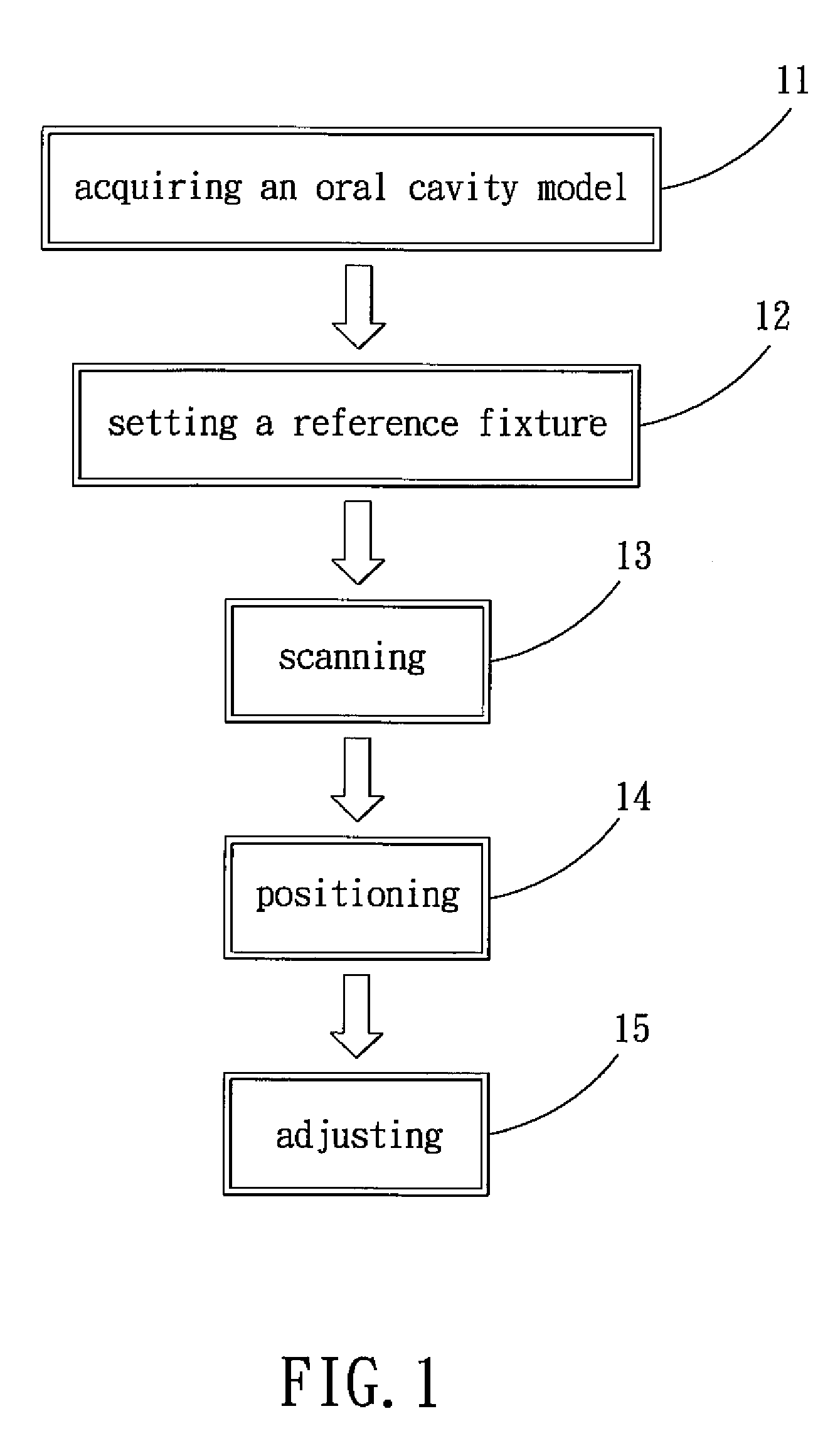
[0029]Please refer to FIG. 1 first, which shows a method for designing an abutment in accordance with the present invention which comprises the steps of: acquiring a mouth model 11; setting a reference abutment device 12; scanning 13; positioning 14; and adjusting 15.

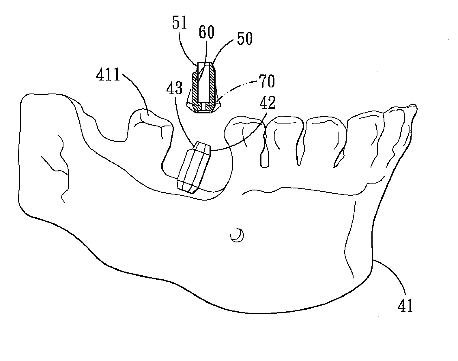
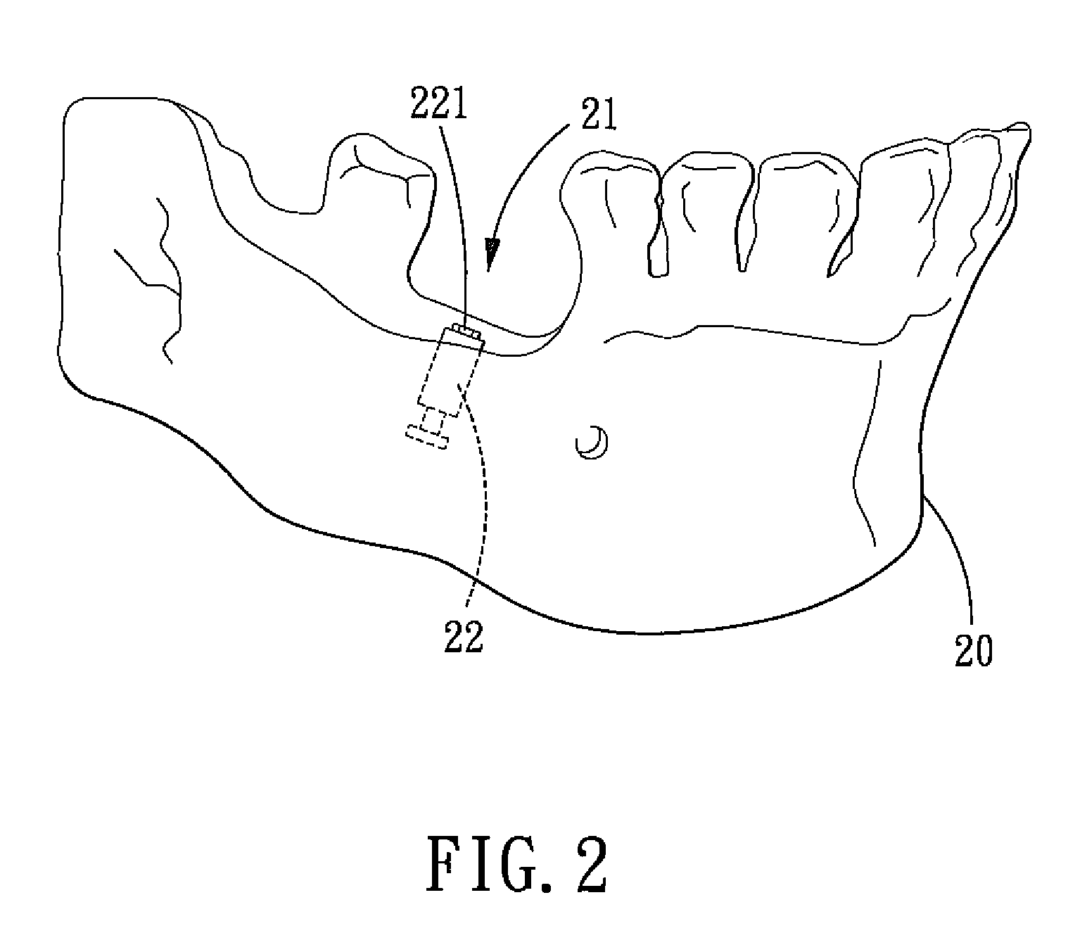
[0030]As shown in FIGS. 2-3B, in the step of acquiring the mouth model 11, which consists of reproducing the inside of the patient's oral cavity to create a mouth model 20, at the dental implant site of the mouth model 20 is an analog 22 having an exposed interface 221. In the present embodiment, the interface 221 of the analog 22 is, for example, in the shape of a hexagon, and the interface 221 can also be in various conventional shapes, such as a triangle, petal shape, and so o...


PUM


Abstract

A method for designing an abutment tooth which mainly comprises the steps of: setting a reference abutment device with a feature on an analog of a mouth model; positioning a digital abutment with the same configuration as the reference abutment device on the analog to obtain the configuration data of the positioning of the digital abutment on the analog; optimally adjusting the digital abutment by using as a reference the configuration digital data without affecting the configuration of the digital abutment and the analog, thus finishing the design of the abutment.

Description

BACKGROUND OF THE INVENTION[0001]1. Field of the Invention[0002]The present invention relates to a dental implant abutment, and more particularly to a method for designing an abutment.[0003]2. Description of the Prior Art[0004]Conventionally, when an abutment is fabricated, in order to fix the artificial tooth at the optimal position, a design software package is utilized to design and modify the configuration of the abutment. To design and modify the abutment, a model of the inside of the patient's mouth needs to be reproduced first. Then the mouth model is scanned by a scanner. Finally, the scanned abutment is designed and modified through the use of a design software package. However, the conventional design and modification of the abutment still has the following disadvantages:[0005]Since the interface of the analog in the mouth model is not obvious, only the digital data of the mouth model can be obtained after scanning, and an accurate digital data of the analog interface cann...

Claims


Application Information

Patent Timeline
Patent Type & Authority Patents(United States)
IPC IPC(8): G06K9/00
CPCA61C8/0001A61C13/0004A61C8/005G16H20/40
Inventor YAU, HONG-TZONGKUO, CHUAN-CHUCHEN, JIUN-RENCHEN, CHINE-AN
Owner POU BIOTECH
Why Eureka
Try Eureka