Television support and mounting kit

a technology for mounting systems and televisions, which is applied in the direction of machine supports, furniture parts, and dismountable cabinets, etc., can solve the problems of increased complexity of flat panel televisions, increased cost, and increased complexity of devices, so as to reduce the number of parts, enhance the connection between the panel tv and the mount structure, and reduce the cost of restocking

Active Publication Date: 2011-12-20
WHALEN LLC
View PDF71 Cites 48 Cited by
  • Summary
  • Abstract
  • Description
  • Claims
  • Application Information

AI Technical Summary

Benefits of technology

[0008]The kit incorporates components for a console with multiple shelves carried on shelf supports. A short spine is provided for use when the console is to be used to support a TV on a stand on the upper shelf. The short spine has mounting openings that engage the shelf supports and extends between the floor or lowest shelf support to the level of the upper most shelf support. A console with three shelves, and therefore three shelf supports, is described as exemplary. The short spine connects to the shelf supports to increase the weight carrying capacity of the shelves and transfer the weight to the floor. Using the short spine allows the user to assemble a console with an upper surface that can carry a conventional (CRT) TV or a panel TV with a stand. The spine is preferably of a rectangular hollow cross-section. The use of a rectangular configuration allows more of the spine to be in contact with the shelf supports than would a circular cross-section, for example. The spine has a plurality of openings in it's rear surface. Because the spine is hollow, these openings permit wires and cabling to be run internally between, for example, electronic equipment on the shelves and the panel TV, thus preventing entanglement of the wires and cables and improving the finished appearance of the installation.
[0010]Spacing the mounting structure and therefore the TV forward of the spine, allows for the incorporation of pivoting and titling mechanisms in the offset arm. The offset arm incorporates mating tilting brackets that are hinged together at their upper ends and free for limited pivoting rotation at the lower ends. This allows the installed TV to be aimed down to face the level at which the TV will be viewed (such as at the level of facing chairs or other furniture). The tilting mechanism is locked in the selected position with fasteners at the lower end of the tilting brackets. The offset arm has a pivot mount at its outer end that cooperates with a pivot mount on the mounting structure to constrain a pivot pin. The pivot mounts collectively provide for pivoting the panel TV about a substantially vertical axis so that the TV can be turned to face the viewing area or to avoid glare.
[0012]The frame incorporates two spaced channels, with U-shaped cross-section, that are oriented to be horizontal when mounted. The channels lie in a plane. The channels are formed with a center web and two sides arranged at right angles to the web. The webs have spaced holes along their length. At least one rail is carried on the frame. In the exemplary embodiment two rails are provided The rails lie in a second plane spaced horizontally from the first plane. This spacing permits the panel TV to be easily lifted and attached as will be described. The channels and rails are joined together in a unitary structure by vertical elements that extend between and are secured to the rails. In the exemplary embodiment the vertical elements and rails are comprised of rectangular tube stock which provides the necessary rigidity at low cost.
[0015]The same XYZ frame can be employed to wall-mount a panel TV. In a wall mount the channels are secured to the wall. Normally it is necessary to locate a pair of studs to insure that connection between the wall and frame is sufficiently strong to support the frame and panel TV. Standard and non-standard stud spacing is accommodated because the channels extend across the full width of the frame and have multiple spaced holes. After the frame is securely mounted to the wall through the frame channels, the panel TV can be lifted so that the engagement hooks pass over the rails and then are lowered with the panel TV to engage and be supported from the rails. The rails are longer than all but the largest TVs and therefore, the TV may be moved horizontally on the rails to center it perfectly relative to, for example, a wall alcove. Stops prevent movement beyond the ends of the rails.
[0016]In both the wall-mount and offset arm mount of the frame, the security of the connection between the panel TV and mount structure is enhanced by a removable latch which is inserted through the vertical channel members above the hooks so that the hooks cannot be lifted off of the rails.
[0017]The invention as described has advantages for the consumer and the retailer. For the retailer stocking the kit avoids having to stock multiple disparate kits, creating a customer service burden, to help the consumer select the right kit, and restocking costs when kits are returned. For the consumer the kit satisfies the mounting requirements for virtually any TV that the consumer might initially use it with, and to TVs that the consumer may acquire in the future. The console may be assembled and used alone with a conventional CRT TV, or with a panel mount on a stand. Then later when the consumer acquires a Vesa standard LCD TV, for example, the consumer can substitute the long spine and offset arm and suspend the panel TV above the console. Should the consumer later acquire a still larger TV, or prefer wall mounting, the XYZ frame can be used. The kit incorporates multi-purpose components to reduce the parts count. All components can be broken down to lie flat for shipping and storage in the minimum space. The kit provides for a floating appearance of the panel above a console and this visual effect is enhanced by being able to hide the wires and cables within the support. Wall mounting is accomplished with minimum need to “work behind” the panel because the panel is merely lifted on the rails and supported without having to manipulate additional fasteners. The use of two engagement hooks on each bracket prevents the panel TV from swinging from the upper rail before it is secured by other means. Other advantages will appear in the following description f the drawings in which like reference numerals refer to like parts throughout and in which:

Problems solved by technology

The introduction of so-called flat panel televisions has added additional complexity to the task of the purchaser to support the television on a suitable stand or to mount it from a wall or above a console.
Although referred to as flat panel TV's, many of these devices have substantial depth and may weight up to 165 lbs or more.
This forces the panel TV retailer to carry a large inventory of incompatible mounting systems, or to leave the consumer to purchase the mounting system directly from the manufacturer.
A purchase direct from the manufacturer forces the consumer to wait for an extended period while the mounting system is shipped and leads to dissatisfaction with the retailer for not stocking the mounting system for the panel TV purchased

Method used


Image

  • Television support and mounting kit
  • Television support and mounting kit
  • Television support and mounting kit

Examples


Embodiment Construction

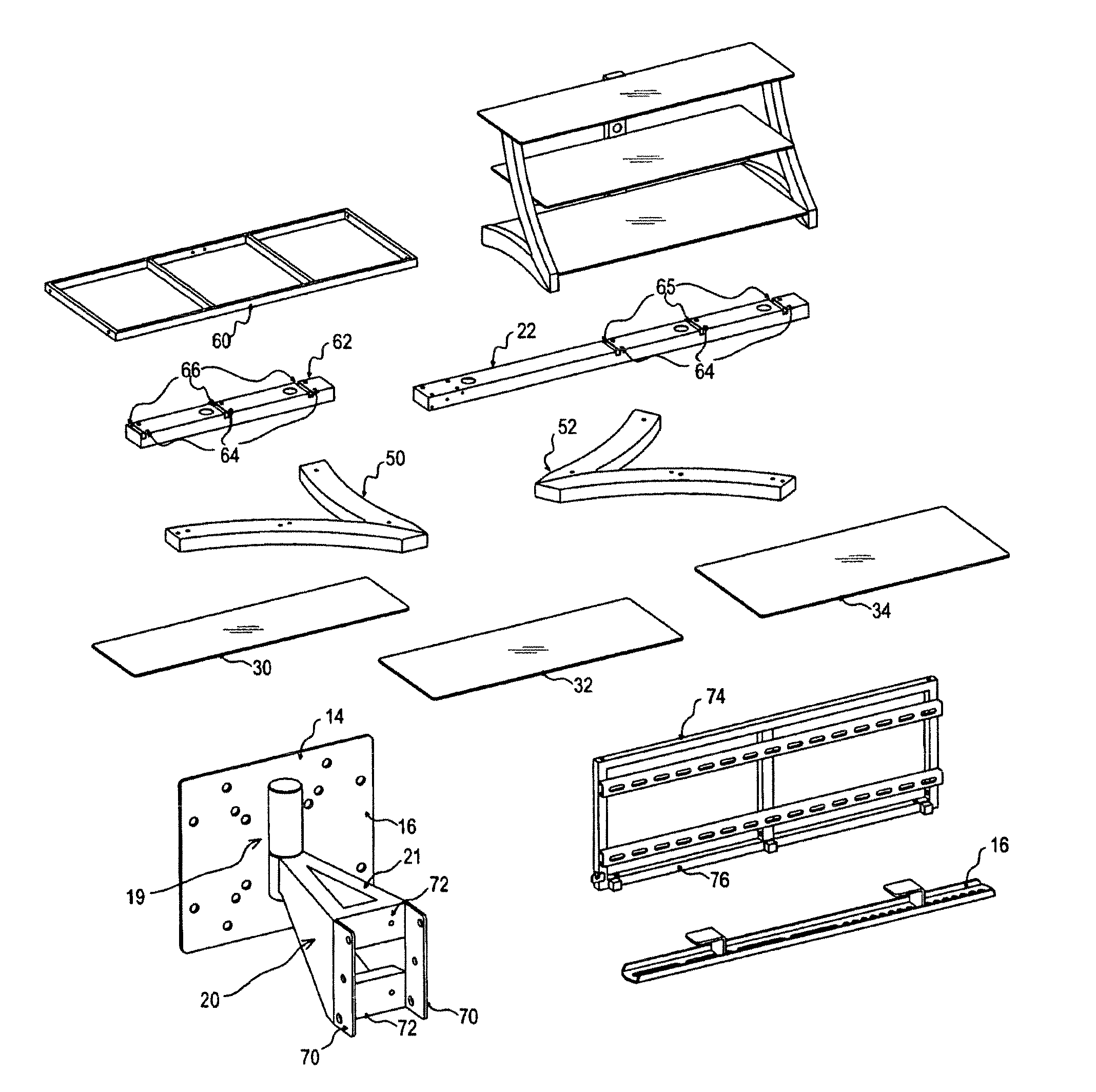
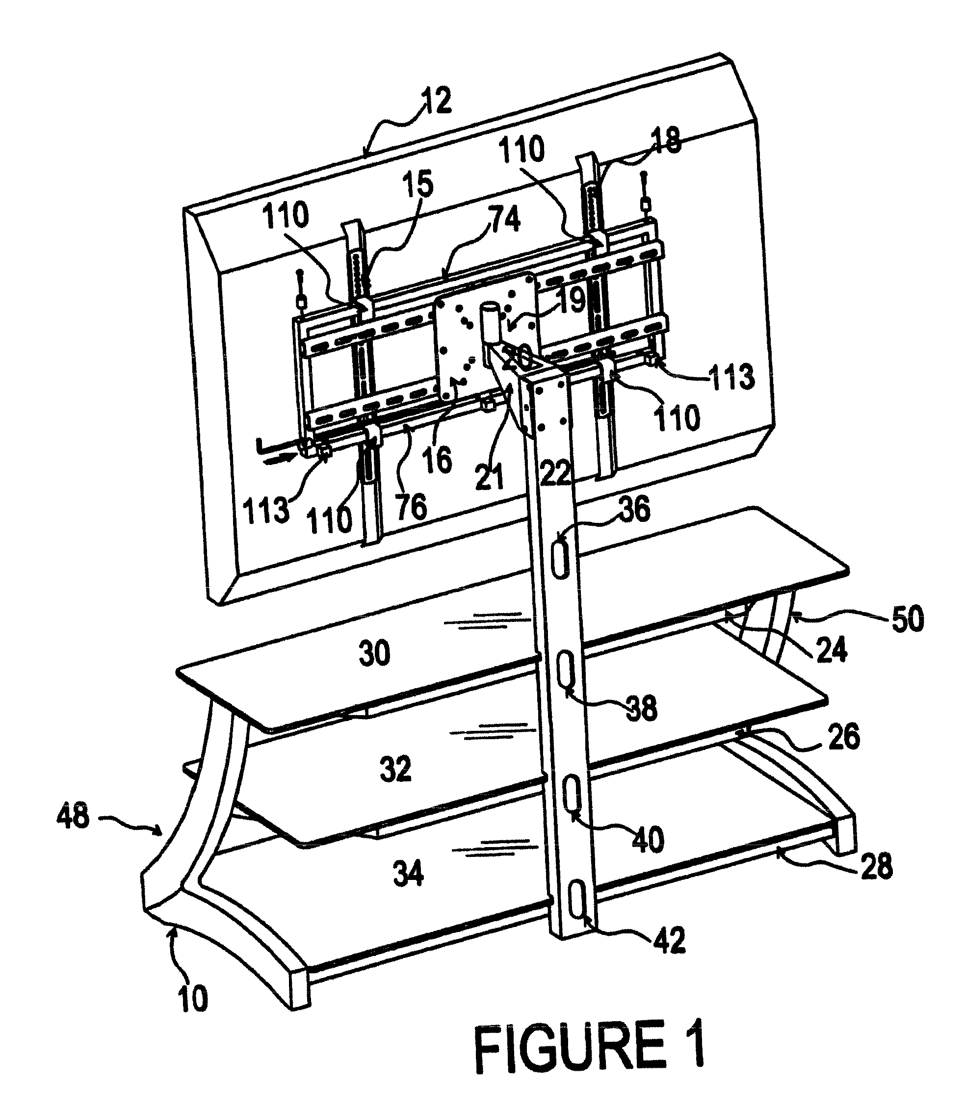
[0031]Referring now to FIG. 1, there is illustrated a console base 10 carrying a plasma panel TV 12 using an XYZ frame 14 connection to the panel TV through panel brackets 15 and 18. The panel brackets incorporated rail engagement hooks 110. When supporting the panel 12, the hooks 110 are received over rails 74 and 76. Limited left and right movement of the panel TV on the frame is possible until the hooks engage the stops 113. The frame is carried by the offset arm 21 through the mounting structure which comprises a mounting plate 16. The mounting plate 16 is connected by pivot bearing 19 and the offset arm 21 to the long spine 22.

[0032]Spine 22, in combination with the side panels 48 and 50, supports the TV 12 and the shelf supports 24, 26 and 28 (partially visible). The shelf supports in turn carry the shelves 30, 32 and 34. The spine contains the wire and cable openings 36, 38, 40 and 42.

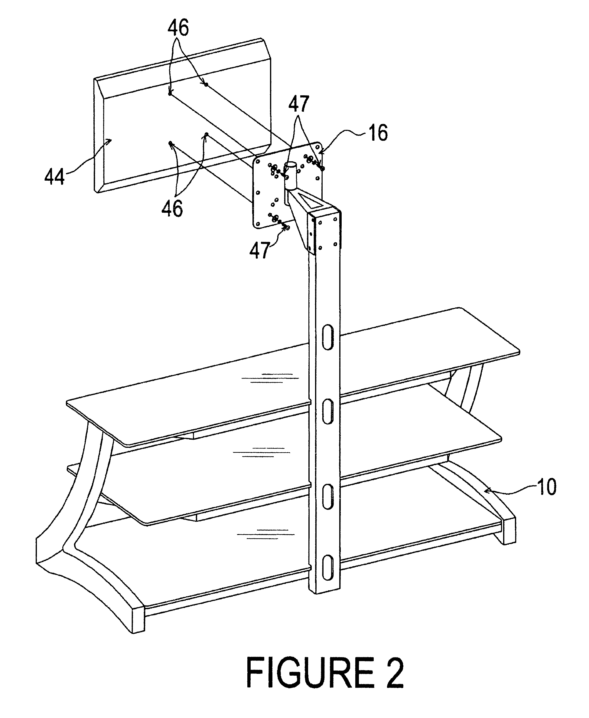
[0033]FIG. 2 shows the same console base 10, supporting a LCD TV 44 that has 4 standard hard...


PUM


Abstract

A universal TV support and mounting kit that accommodates the principal varieties of TVs that have to be mounted or supported, namely CRT type and two panel types (plasma and LCD), in a single kit. The kit that allows the consumer to employ any of the three modes of support, namely stand mount, console mount and wall mount. The console mount incorporates a vertical spine and a gooseneck mount. A frame is provided that can be attached to the gooseneck mount or to a wall. Pivoting and tilting is accommodated by the gooseneck mount.

Description

CROSS-REFERENCE TO RELATED APPLICATIONS[0001]The instant application is a Continuation In Part of U.S. utility application Ser. No. 11 / 890,828 filed Aug. 8, 2007 now abandoned entitled “TELEVISION SUPPORT AND MOUNTING KIT.”FIELD OF THE INVENTION[0002]The invention is in the field of mounting systems for televisions to be wall-mounted or carried on a base (console).BACKGROUND OF THE INVENTION[0003]The introduction of so-called flat panel televisions has added additional complexity to the task of the purchaser to support the television on a suitable stand or to mount it from a wall or above a console. As used herein televisions (TVs) should be understood to include monitors without tuners and televisions with built in tuners. Although referred to as flat panel TV's, many of these devices have substantial depth and may weight up to 165 lbs or more. Flat panel TV's (referred to herein as panel TV's) represent a substantial investment for the purchaser and therefore mounting them without...

Claims


Application Information

Patent Timeline
Patent Type & Authority Patents(United States)
IPC IPC(8): A47B23/00
CPCF16M11/00F16M11/08F16M11/10F16M11/2014A47B81/00F16M13/02F16M2200/022F16M2200/028Y10S248/923A47B81/06A47B81/065A47B97/001A47B47/00
Inventor WHALEN, KENNETHJONES, PAUL R.
Owner WHALEN LLC
Why Eureka
Try Eureka