Optical scanner and image-forming device

a technology of optical scanner and image forming device, which is applied in the direction of printing, inking apparatus, instruments, etc., can solve the problems of reducing the quality of the electrostatic latent image formed thereon, reducing the width of light, and increasing the rotational speed of the polygon mirror

Active Publication Date: 2011-12-20
BROTHER KOGYO KK
View PDF33 Cites 6 Cited by
  • Summary
  • Abstract
  • Description
  • Claims
  • Application Information

AI Technical Summary

Benefits of technology

[0009]It is an object of the present invention to provide an optical scanner capable of reducing vibrations in an scanning optical system due to vibrations of a deflecting unit without increasing the structural complexity of a support frame, and an image-forming device equipped with this optical scanner. It is another object of the present invention to provide an optical scanner and an image-forming device capable of increasing the rotational speed of a deflecting unit while preventing stray light from being incident on a scanning surface or optical sensor.
[0012]According to a different aspect of the present invention, there is provided an optical scanner including a light source that emits a light, a deflecting unit that deflects and scans the light in a main scanning direction, and a shielding rib disposed near the deflecting unit and between the light source and the deflecting unit. The shielding rib is formed with a first aperture that allows the passage of the light from the light source while restricting the width of the light.
[0014]According to a different aspect of the preset invention, there is provided an image-forming device including a light source emitting a light, a deflecting unit that deflects and scans the light in the main scanning direction, and a shielding rib disposed near the deflecting unit between the light source and the deflecting unit. The shielding rib is formed with a first aperture that allows the passage of the light from the light source while restricting the width of the light.

Problems solved by technology

However, increasing the rotational speed of the polygon mirror generates greater vibrations in the polygon mirror unit.
These vibrations vibrate the scanning optical system supported on the support frame, which produce displacement in the laser beam.
This displacement causes irregularities in the scanning position of the laser beam on the surface of the photosensitive member, degrading the quality of the electrostatic latent image formed thereon.
However, adding more reinforcing ribs increases the complexity of the support frame structure, leading to increased costs for manufacturing the support frame.

Method used


Image

  • Optical scanner and image-forming device
  • Optical scanner and image-forming device
  • Optical scanner and image-forming device

Examples


first embodiment

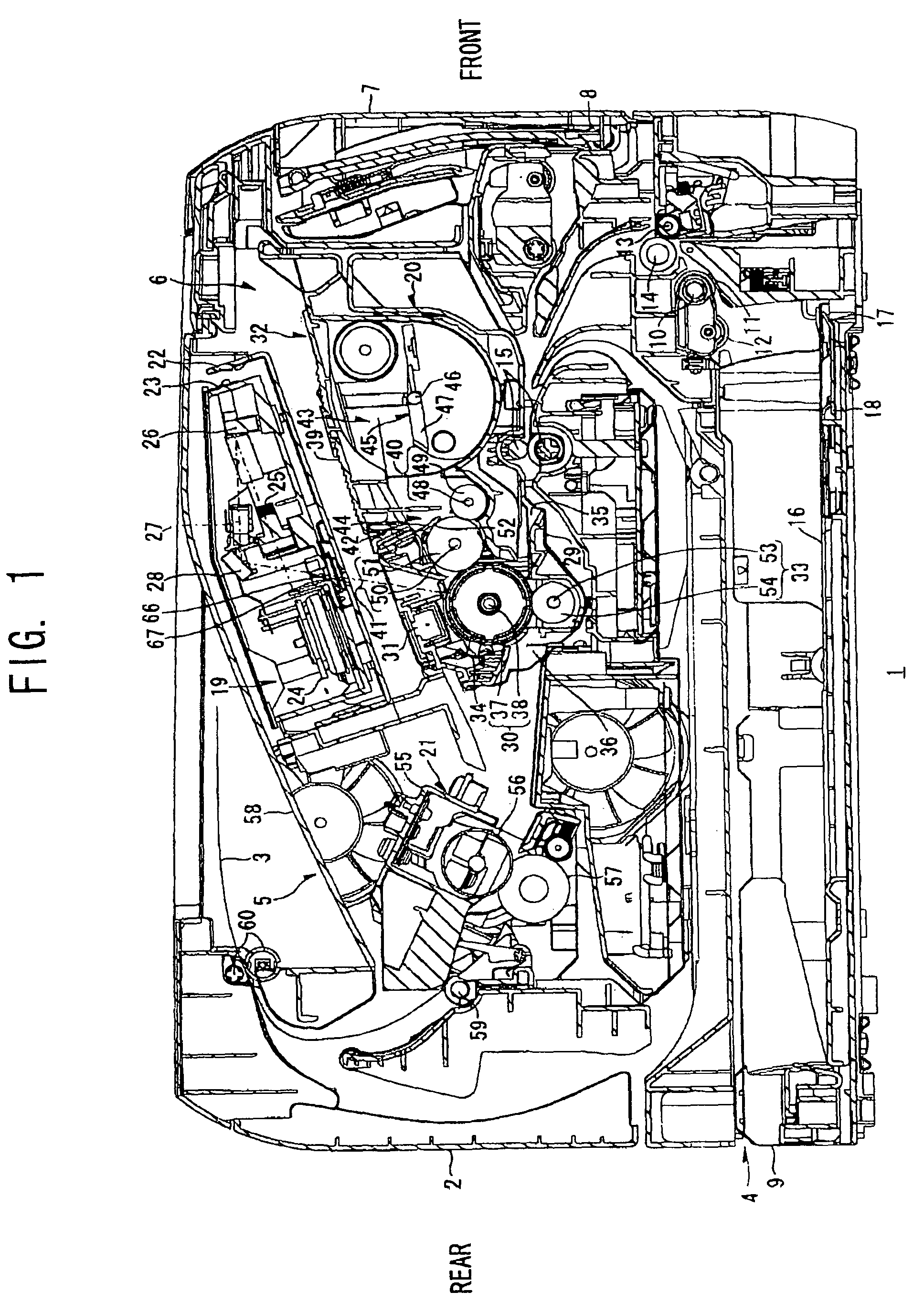
[0028]First, a laser printer 1 according to the present invention will be described.

[0029]As shown in FIG. 1, the laser printer 1 includes a feeding unit 4 for supplying sheets of paper 3, an image-forming unit 5 for forming images on the paper 3 supplied by the feeding unit 4, and a main casing 2 housing the feeding unit 4 and the image-forming unit 5.

[0030]The laser printer 1 also includes an access opening 6 formed in one side wall of the main casing 2 for inserting and removing a process cartridge 20 described later, and a front cover 7 capable of opening and closing over the access opening 6. The front cover 7 is rotatably supported by a cover shaft 8 inserted through a bottom edge of the front cover 7. Accordingly, when the front cover 7 is rotated closed about the cover shaft 8, the front cover 7 covers the access opening 6 as shown in FIG. 1. When the front cover 7 is rotated open about the cover shaft 8, the access opening 6 is exposed, enabling the process cartridge 20 to ...

second embodiment

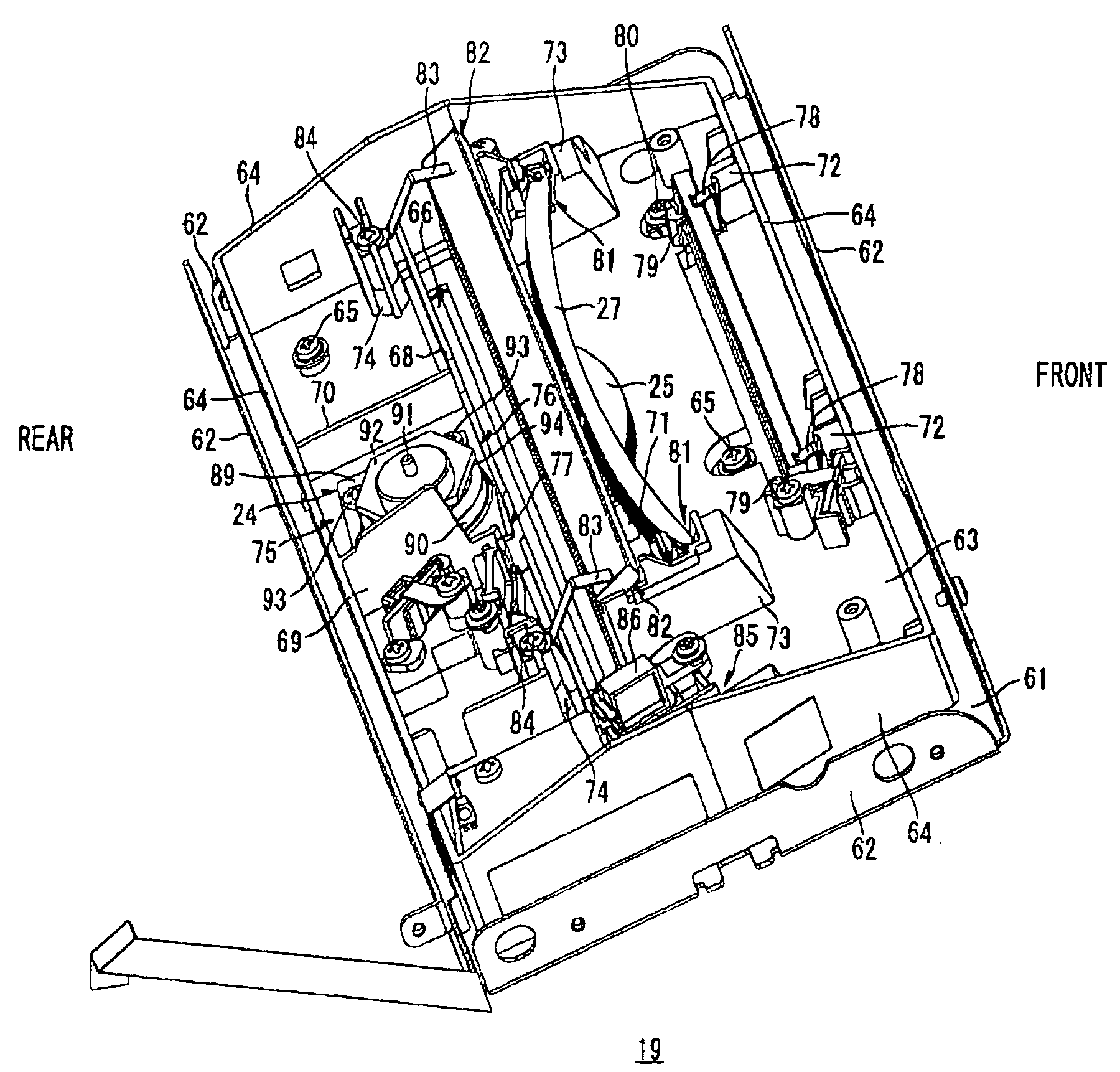
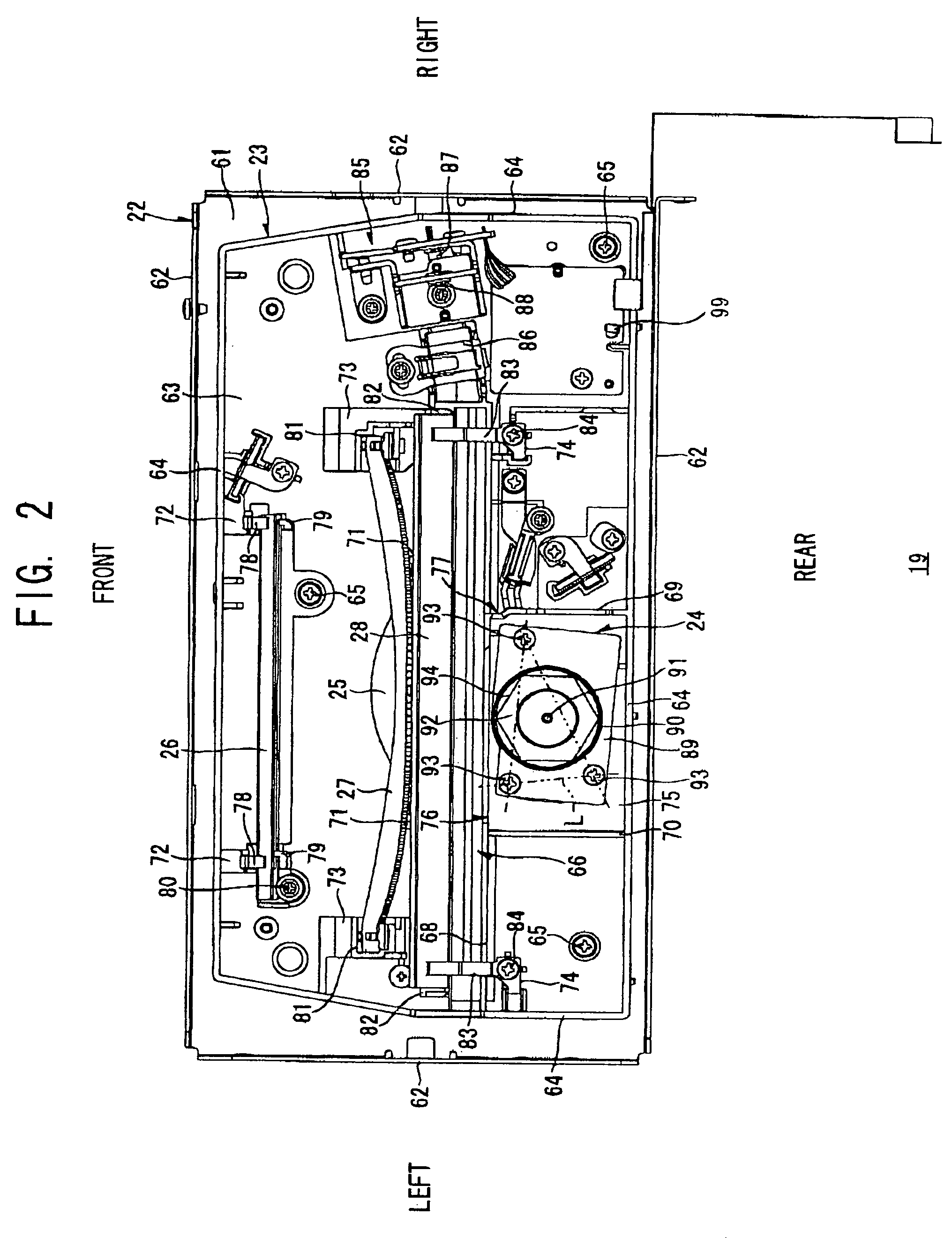
[0129]Next, a scanning unit 119 according to the present invention will be described FIG. 7 is a perspective view schematically illustrating the scanning unit 119, wherein like parts and components are designated with the same reference numerals to avoid duplicating description.

[0130]In the structure shown in FIG. 7, an aperture plate 96 is disposed between the light source 85 and the cylindrical lens 86. The aperture plate 96 is formed with a rectangular aperture 95 that is wider than the input side opening 77 in the main scanning direction. A laser beam emitted from the light source 85 first passes through the aperture 95 of the aperture plate 96 and subsequently passes through the cylindrical lens 86 and the input side opening 77 before striking the polygon mirror 92.

[0131]By directing the laser beam through the aperture 95 of the aperture plate 96, this construction can restrict the width of the laser beam in both the main scanning direction and the subscanning direction. In oth...

third embodiment

[0133]Next, a scanning unit 219 according to the present invention will be described. FIG. 8 is a perspective view schematically illustrating the scanning unit 219, wherein like parts and components are designated with the same reference numerals to avoid duplicating description.

[0134]In the structure shown in FIG. 8, an aperture plate 98 is disposed between the polygon mirror 92 and the fθ lens 25 The aperture plate 98 is formed with a rectangular aperture 97 elongated in the main scanning direction. With this construction, the laser beam deflected and scanned by the polygon mirror 92 passes through the aperture 97 of the aperture plate 98 prior to being incident on the fθ lens 25. Therefore, the aperture 97 of the aperture plate 98 restricts the width of the laser beam in the subscanning direction before the laser beam reaches the fθ lens 25.

[0135]With this construction, the input side opening 77 of the front-to-rear rib 69 restricts the width of the laser beam in the main scannin...


PUM


Abstract

An scanning unit scanner includes a light source and a polygon mirror unit. A front-to-rear rib is disposed between the light source and the polygon mirror unit and near the polygon mirror unit. An input side opening having a slit shape is formed as a cutout in the top edge of the front-to-rear rib. When laser light from the light source passes through the input side opening, the input side opening restricts the width of the light in a main scanning direction.

Description

BACKGROUND OF THE INVENTION[0001]1. Field of the Invention[0002]The present invention relates to an image-forming device, such as a laser printer, and an optical scanner provided in the image-forming device.[0003]2. Description of the Related Art[0004]Conventional image-forming devices, such as laser printers are commonly equipped with an optical scanner functioning to form electrostatic latent images on a photosensitive member based on image data by scanning a laser beam over the surface of the photosensitive member.[0005]One such optical scanner disclosed in Japanese unexamined patent application publication No. 2005-62892 includes a semiconductor laser; a polygon mirror unit having a polygon mirror formed in the shape of a flat polygonal column, each side surface of which is a reflecting surface for reflecting a laser beam, and a polygon motor for driving the polygon mirror to rotate; and an scanning optical system for forming an image on the surface of the photosensitive member ...

Claims


Application Information

Patent Timeline
Patent Type & Authority Patents(United States)
IPC IPC(8): G02B26/08B41J27/00G02B26/12G02B26/10B41J2/435
CPCG02B26/08G02B26/124
Inventor KATO, RYOTAMORI, SHOGO
Owner BROTHER KOGYO KK
Why Eureka
Try Eureka