Ink-jet recording head

a liquid discharge head and recording head technology, applied in printing and other directions, can solve the problems of adverse influence on the discharge characteristics of ink droplets and image quality, pressure loss generation, adverse influence on electrothermal transducers, etc., to prevent the reduction of the discharge speed of liquid droplets, reduce the flow rate of liquid droplets, and reduce the pressure loss in the flow of liquid toward the discharge ports

Inactive Publication Date: 2011-12-27
CANON KK
View PDF38 Cites 3 Cited by
  • Summary
  • Abstract
  • Description
  • Claims
  • Application Information

AI Technical Summary

Benefits of technology

[0015]According to the above-described configuration, the pressure loss in the flow of the liquid toward the discharge ports can be minimized. As a result, even if the fluid resistance in the direction of the discharge ports at the first discharge-port portion is increased by further reducing the size of the discharge ports at the distal ends of the nozzles, it is possible to suppress the reduction of the flow rate in the direction of the discharge ports when discharging the liquid, and thereby prevent reduction of the discharge speed of the liquid droplets. In the above-described configuration, it is possible to increase the volume of the second discharge-port portion without hindering a high-density arrangement of the discharge ports. Accordingly, it is possible to realize a high-density arrangement of the discharge ports while suppressing reduction of the discharge speed, and thereby provide a very precise recorded image.

Problems solved by technology

However, this method has, for example, the peculiar problems that the volume of ink droplets to be ejected changes due to storage of heat generated by the electrothermal transducers within the recording head, cavitation produced by disappearance of bubbles adversely influences the electrothermal transducers, and the discharge characteristics of ink droplets and the image quality are adversely influenced by bubbles of air dissolved within the ink that remains within the recording head.
At that time, part of the pressure due to bubble generation in the ink is applied toward the supply channel side, or a pressure loss is generated due to friction with the inner wall of the discharge port.
This phenomenon adversely influences ink discharge, and is more pronounced as the amount of ink contained in the discharged ink droplet is smaller (i.e., as the volume of the discharged droplet is smaller).

Method used


Image

  • Ink-jet recording head
  • Ink-jet recording head
  • Ink-jet recording head

Examples


first embodiment

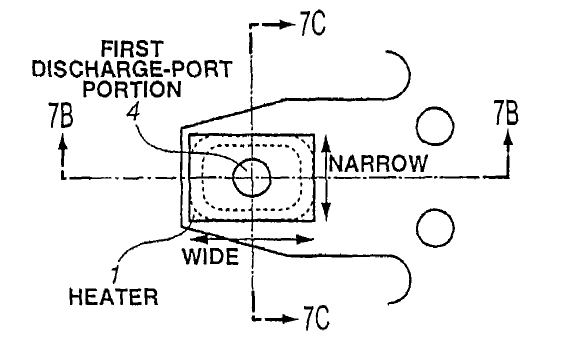
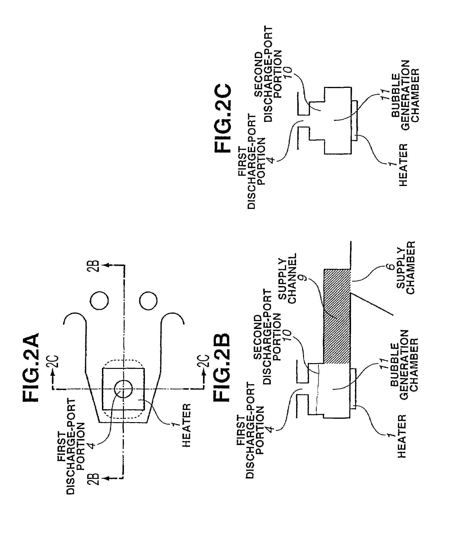
[0043]FIGS. 2A-2C illustrate the structure of a nozzle of an ink-jet recording head according to a first embodiment of the present invention. FIG. 2A is a plan perspective diagram in which one of a plurality of nozzles of the ink-jet recording head is seen from a direction perpendicular to a main surface (a surface where the channel-configuration substrate of the element substrate 2 is connected) of the element substrate 2; FIG. 2B is a cross-sectional view taken along line A-A shown in FIG. 2A; and FIG. 2C is a cross-sectional view taken along line B-B shown in FIG. 2A.

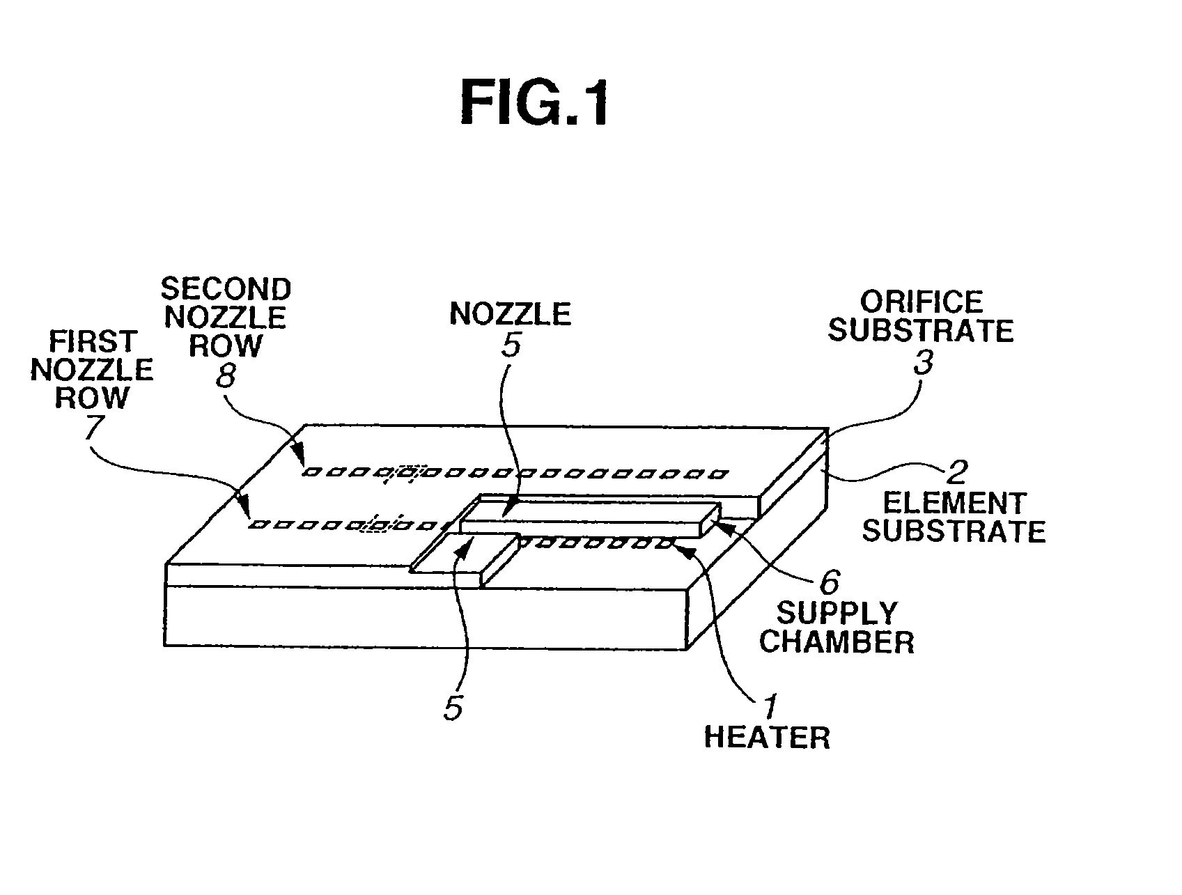
[0044]As shown in FIG. 1, the recording head having the nozzle structure of the first embodiment includes the element substrate 2 on which the plurality of heaters 1, each serving as an electrothermal transducer, are provided, and the channel-configuration substrate 3 that constitutes a plurality of ink channels by being connected to the main surface of the element substrate 2 in a laminated state.

[0045]The element s...

second embodiment

[0053]In a second embodiment of the present invention, a nozzle structure is adopted in which the second discharge-port portion has a tapered shape in order to reduce stagnation of ink at the second discharge-port portion. Portions different from the first embodiment will now be mainly described with reference to FIGS. 3A-3C.

[0054]FIGS. 3A-3C illustrate the structure of a nozzle of an ink-jet recording head according to the second embodiment. FIG. 3A is a plan perspective diagram in which one of a plurality of nozzles of the ink-jet recording head is seen from a direction perpendicular to the main surface of the element substrate 2; FIG. 3B is a cross-sectional view taken along line A-A shown in FIG. 3A; and FIG. 3C is a cross-sectional view taken along line B-B shown in FIG. 3A.

[0055]As is apparent from FIGS. 3A-3C, as in the first embodiment, in the ink-jet recording head of the second embodiment, the second discharge-port portion 10 has an end surface that includes a border porti...

third embodiment

[0057]An object of a third embodiment of the present invention is to reduce the region of ink stagnation in order to reduce variations in the discharge volume. In the second embodiment, the cross section of the second discharge-port portion is substantially rectangular. In the third embodiment, however, the cross section of the second discharge-port portion is elliptical.

[0058]Portions in the third embodiment that are different from the first embodiment will now be mainly described with reference to FIGS. 4A-4C.

[0059]FIGS. 4A-4C illustrate the structure of a nozzle of an ink-jet recording head according to the third embodiment. FIG. 4A is a plan perspective diagram in which one of a plurality of nozzles of the ink-jet recording head is seen from a direction perpendicular to the main surface of the element substrate 2; FIG. 4B is a cross-sectional view taken along line A-A shown in FIG. 4A; and FIG. 4C is a cross-sectional view taken along line B-B shown in FIG. 4A.

[0060]As shown in ...


PUM


Abstract

An ink-jet recording head includes a discharge-port portion including a first discharge-port portion continuing from a discharge port, and a second discharge-port portion communicating the first discharge-port portion with a bubble generation chamber. The second discharge-port portion has an end surface that includes a border portion bordering the first discharge-port portion and is parallel to a main surface of an element substrate. The cross-sectional area of the second discharge-port portion, anywhere from an opening surface facing the bubble generation chamber to an end surface facing the first discharge-port portion, that is parallel to the main surface of the element substrate, is larger than the area of the border portion. The cross-section of the opening surface of the second discharge-port portion has a length in a direction perpendicular to an arrangement direction of the discharge ports that is greater than its length in a direction parallel to the arrangement direction.

Description

[0001]This application is a continuation of U.S. patent application Ser. No. 10 / 747,204, filed Dec. 30, 2003, which has been allowed, and the entire contents of which are incorporated by reference herein.BACKGROUND OF THE INVENTION[0002]1. Field of the Invention[0003]The present invention relates to a liquid-discharge head for performing recording on a recording medium by discharging droplets of a liquid, such as ink, or the like. More particularly, the invention relates to a liquid discharge head for performing ink-jet recording.[0004]2. Description of the Related Art[0005]An ink-jet recording method is one of so-called non-impact recording methods. In the ink-jet recording method, noise generated during recording is negligibly small, and high-speed recording can be performed. Furthermore, recording can be performed on various recording media. For example, on so-called ordinary paper, ink is fixed without requiring particular processing, and a very precise image can be inexpensivel...

Claims


Application Information

Patent Timeline
Patent Type & Authority Patents(United States)
IPC IPC(8): B41J2/05B41J2/14B41J2/145
CPCB41J2/1404B41J2/1433B41J2/145B41J2002/14387B41J2002/14403B41J2002/14467B41J2002/14475
Inventor TOMIZAWA, KEIJIMURAKAMI, SHUICHI
Owner CANON KK
Why Eureka
Try Eureka