Power tool

a power tool and tool body technology, applied in the direction of dynamo-electric machines, electrical equipment, supports/enclosements/casings, etc., can solve the problem of degrading cooling performance, and achieve the effect of excessive load

Active Publication Date: 2011-12-27
KOKI HLDG CO LTD
View PDF28 Cites 31 Cited by
  • Summary
  • Abstract
  • Description
  • Claims
  • Application Information

AI Technical Summary

Benefits of technology

[0005]It is an object of the invention to provide a power tool securing the cooling performance without providing the heat individual radiating member.
[0009]By such a configuration, since the cooling air is taken in through the suction port at any time, the atmosphere around the suction port can be made equivalent to the outside air at any time. Thereby, the cooling performance from the heat radiating surface is enhanced, and the cooling can be made stably.
[0011]By such a configuration, the cooling air flown inside the air passage is directly applied on the heat radiating surface. Thereby, the cooling performance on the heat radiating surface is enhanced, and the cooling can be made more suitably.
[0013]By such a configuration, the switching element is projected without contacting with other members, and prevented from undergoing an external force such as an urging force from other members. Hence, an excessive load is suppressed on the connection part between the electric circuit and the board.

Problems solved by technology

However, in these power tools, since heat generated in the output transistor is conveyed to the heat radiating member and radiated, conduction of heat is not made excellently if there is a gap between the output transistor and the heat radiating member, whereby the cooling performance may be degraded.
Generally, the output transistor is fixed on the board by three legs, but if the urging force is applied, the root of leg may be broken to cause a disconnection.

Method used


Image

  • Power tool
  • Power tool
  • Power tool

Examples


Embodiment Construction

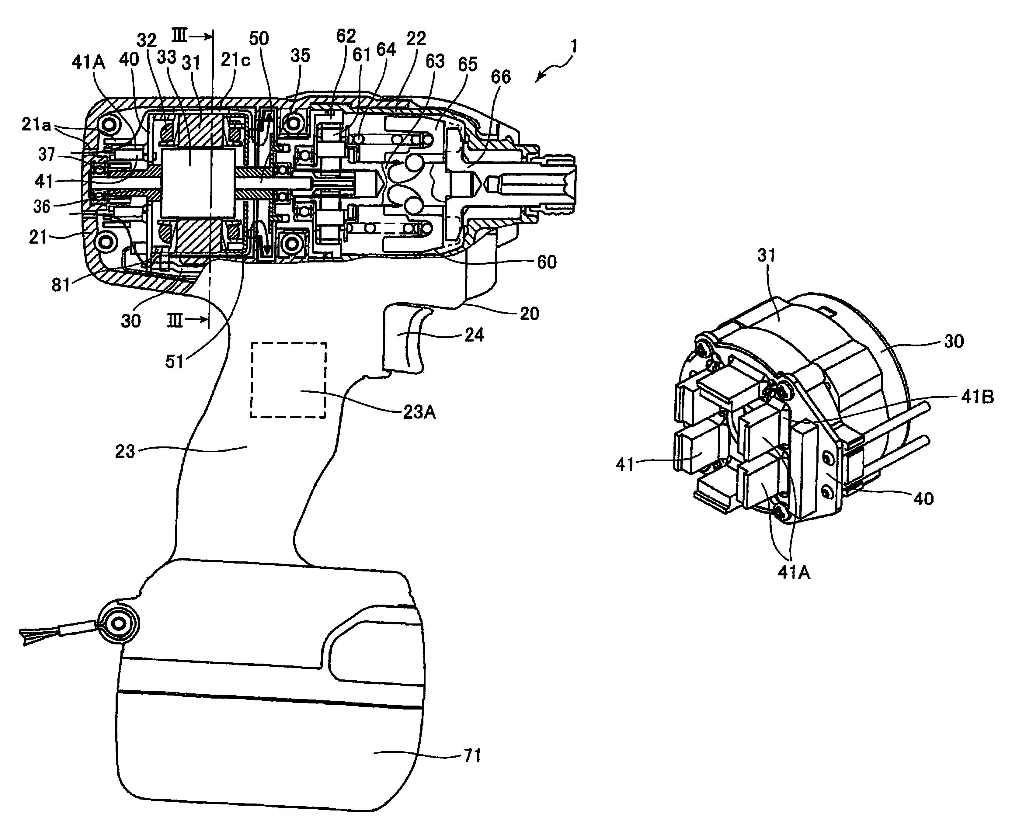
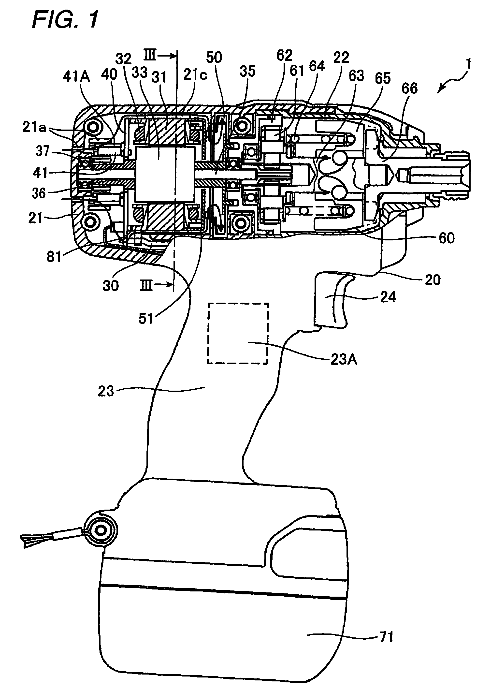
[0018]A power tool according to an embodiment of the present invention will be described below with reference to FIGS. 1 to 4. An impact driver 1 that is the power tool as shown in FIG. 1 is mainly composed of a housing 20, a motor 30, a circuit board 40, and a power transmission device 60.

[0019]The housing 20 is composed of a motor housing portion 21, a power transmission housing portion 22, and a handle housing portion 23. In this embodiment, a forward direction is defined as the direction from the motor housing portion 21 to the power transmission housing portion 22, and a backward direction is defined as the opposite direction. A downward direction is defined as the direction, orthogonal to this longitudinal direction, along which the handle housing portion 23 extends.

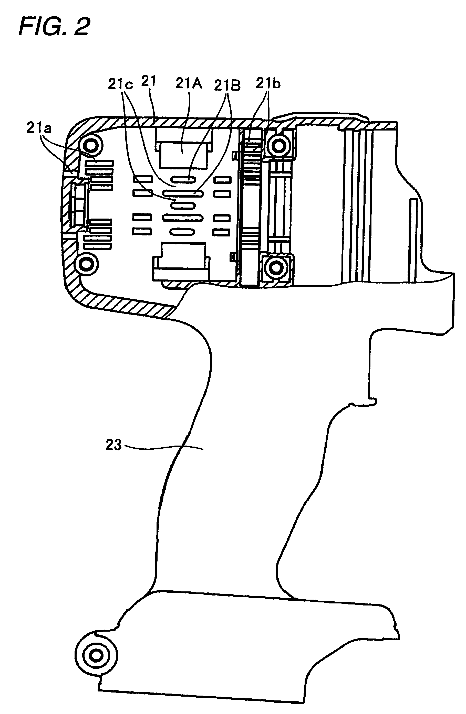
[0020]The motor housing portion 21 has a cylindrical shape, and accommodates the motor 30 and the circuit board 40. An air inflow hole 21a for permitting the air to flow from outside the housing 20 is formed at an ...


PUM


Abstract

According to an aspect of the present invention, there is provided a power tool including: a housing having a suction port formed thereon to introduce an cooling air from an outside of the housing; and a brushless motor that is housed in the housing and has an electric circuit, the electric circuit having a heat radiating surface, wherein the heat radiating surface is disposed in a neighborhood of the suction port.

Description

TECHNICAL FIELD[0001]An aspect of the present invention relates to a power tool.BACKGROUND ART[0002]A brushless motor (DC motor) for use as motive power of a power tool can be reduced in size, and have a longer life, because there is no need for electrical connection to a rotor attached to the rotation shaft using a brush and a commutator. To drive the brushless motor, an inverter circuit board (motor drive circuit board) that is an electric circuit is required.[0003]The inverter circuit board includes a switching element, and needs some cooling measures, because an output transistor of the switching element supplies a drive signal of large current to a stator coil and generates a large amount of heat. JP-A-2004-357371, JP-A-2005-176451 and JP-A-2004-122343 disclose a cooling structure for the inverter circuit board, in which a heat radiating member is fixed to the output transistor.[0004]However, in these power tools, since heat generated in the output transistor is conveyed to the...

Claims


Application Information

Patent Timeline
Patent Type & Authority Patents(United States)
IPC IPC(8): H02K7/14
CPCB25F5/008H02K9/06H02K7/145H02K5/20H02K5/207
Inventor OOMORI, KATSUHIROKOMURO, YOSHIHIROYOSHIDA, KENICHIROUIWATA, KAZUTAKA
Owner KOKI HLDG CO LTD
Why Eureka
Try Eureka