DC-Link capacitor and manufacturing method

A manufacturing method and technology of capacitors, applied in capacitors, fixed capacitors, wire wound capacitors, etc., can solve the problems of high equivalent series resistance, equivalent series inductance, affecting the service life of capacitors, low production efficiency, etc., and achieve low equivalent series resistance. resistance, reducing the equivalent series inductance, and improving production efficiency

Inactive Publication Date: 2016-12-07
扬州日精电子有限公司
View PDF7 Cites 2 Cited by
  • Summary
  • Abstract
  • Description
  • Claims
  • Application Information

AI Technical Summary

Problems solved by technology

[0005] The above process has the following two problems: 1. The stack welding produces high equivalent series resistance and equivalent series inductance, which is not conducive to heat dissipation during operation and affects the service life of the capacitor; 2. Multiple core stack welding only Manual welding can be used, and the production efficiency is low

Method used


Image

  • DC-Link capacitor and manufacturing method
  • DC-Link capacitor and manufacturing method
  • DC-Link capacitor and manufacturing method

Examples


Embodiment Construction

[0025] Embodiments of the technical solutions of the present invention will be described in detail below in conjunction with the accompanying drawings. The following examples are only used to illustrate the technical solution of the present invention more clearly, so they are only examples, and should not be used to limit the protection scope of the present invention.

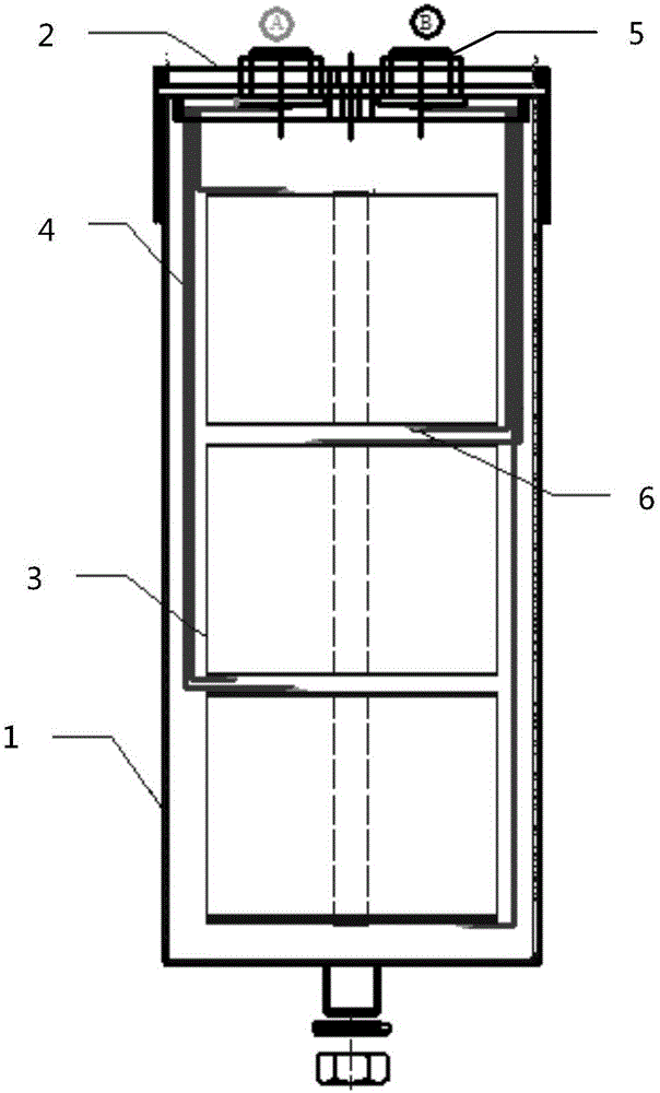
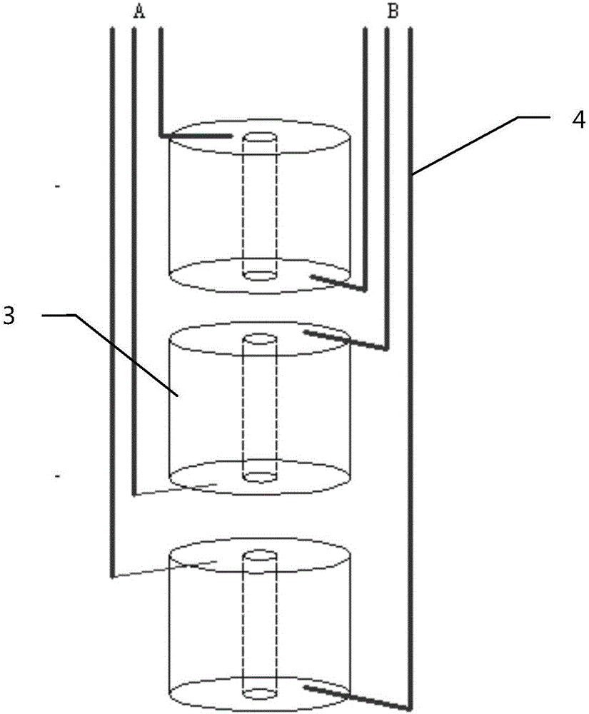
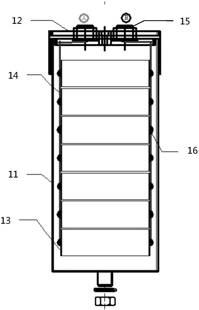
[0026] Such as image 3 , Figure 4 As shown, the structure of the DC-Link capacitor of the present invention includes: a housing 11; 7 cores 13 superimposed on each other accommodated in the housing 11; located on the side of the core 13 through 28 solder joints (14 on one side) 16 and the core The two copper strips 14 connected by the sub 13; the cover plate 12 forming a closed space with the shell 11; the two electrodes 15 welded to the ends of the two copper strips 14 on the cover plate 12, the ends of the copper strips 14 It is curved. The end of the bent copper strip 14 is more convenient for welding w...


PUM


Abstract

The invention belongs to the technical field of power electronic capacitors, and mainly provides a DC-Link capacitor and a manufacturing method. The capacitor comprises a shell, multiple mutually laminated cores, multiple copper strips, a cover plate and an electrode, wherein the multiple mutually laminated cores are in the shell; the multiple copper strips are positioned on the side surface of the cores and connected with the cores through welding spots; the cover plate forms a closed space with the shell; and the electrode is arranged on the cover plate and welded with the tail ends of the copper strips. In a manufacturing process, because all the connection welding spots of the copper strips and the cores are positioned on the side surface of the cores, the fact that welding is completed through an automatic welding machine becomes possible; and thus, the production efficiency of the DC-Link capacitor is improved.

Description

technical field [0001] The invention relates to the technical field of power electronic capacitors, in particular to a DC-Link capacitor and a manufacturing method. Background technique [0002] With the introduction of the national new energy strategy, the country regards electric vehicles, high-speed trains, solar energy, and wind power generation as national priority development industries, and the development of the above industries is inseparable from DC-Link DC filter capacitors. [0003] figure 1 A schematic diagram of the structure of the existing DC-Link film capacitor is shown. The existing DC-Link film capacitor adopts a circular dry structure, including: an aluminum circular shell 1, a polysulfide plastic cover plate 2, one or more ordinary The circular capacitor core 3 wound by film, the copper strip 4 connecting the core 3 and the electrode 5 , and the copper strip 4 and the core 3 are connected by solder joints 6 . [0004] figure 2 It shows the core conne...

Claims


Application Information

Patent Timeline
IPC IPC(8): H01G4/38H01G4/32H01G4/232
CPCH01G4/385H01G4/232H01G4/32
Inventor 陈重生程海超张淮鑫
Owner 扬州日精电子有限公司
Why Eureka
Try Eureka