Magnetic sensor

a technology of magnetic sensors and sensors, applied in the field of magnetic sensors, can solve problems such as failure to obtain a sufficient potential output and unsatisfactory, and achieve the effect of increasing potential outpu

Active Publication Date: 2011-12-27
TDK CORPARATION
View PDF14 Cites 21 Cited by
  • Summary
  • Abstract
  • Description
  • Claims
  • Application Information

AI Technical Summary

Benefits of technology

[0009]It is also conceivable to increase the output by increase in the electric current, but simple increase in the current value will result in increase in resistance in opposed surfaces between the magnetization fixed layer and the channel layer, with increase in current density. As a result, spins become less likely to be injected from the magnetization fixed layer into the channel layer, resulting in a failure in obtaining a sufficient potential output.
[0024]Preferably, a material of the channel layer is a material containing at least one element selected from the group consisting of B, C, Mg, Al, Cu, and Zn. Since these materials have a long spin diffusion length and relatively small electroconductivity, it becomes feasible to suitably realize the function of the channel layer as a spin accumulation layer. The material of the channel layer is also preferably a semiconductor compound containing any one of Si, ZnO, and GaAs. Since these semiconductor compounds have a longer spin diffusion length, they are more suitable for letting the channel layer function as a spin accumulation layer and the potential output can be made higher than with the channel layers using the aforementioned metals or the aforementioned alloys.

Problems solved by technology

Another conceivable method is a method of providing an insulating layer between the magnetization free layer and magnetization fixed layer and the channel layer, in order to inject more spin-polarized electrons from the magnetization fixed layer into the channel layer, but these were not satisfactory.
As a result, spins become less likely to be injected from the magnetization fixed layer into the channel layer, resulting in a failure in obtaining a sufficient potential output.

Method used


Image

  • Magnetic sensor
  • Magnetic sensor
  • Magnetic sensor

Examples


first embodiment

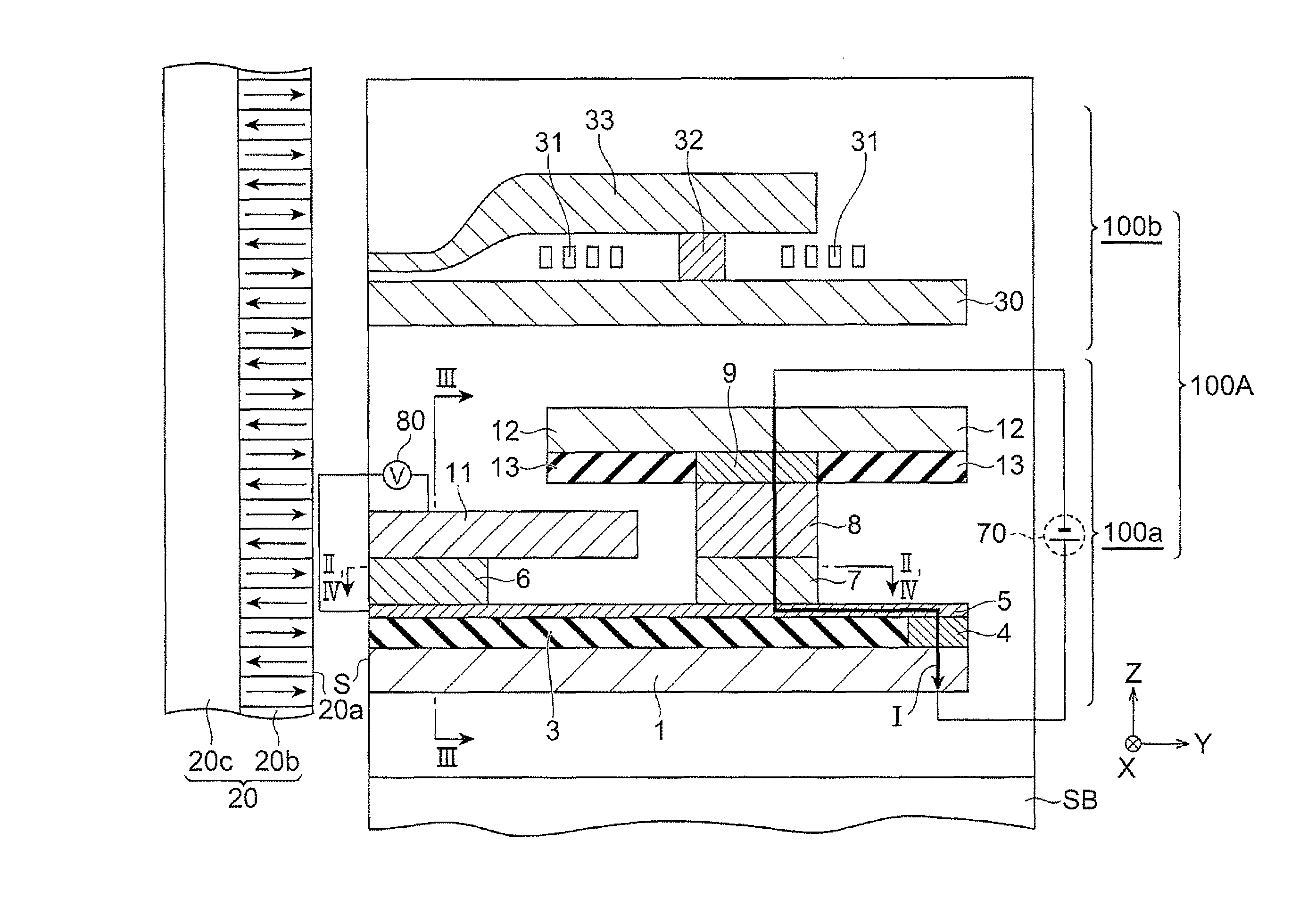
[0031]A thin-film magnetic recording / reproducing head 100A will be described below as an example of a magnetic sensor according to the first embodiment.

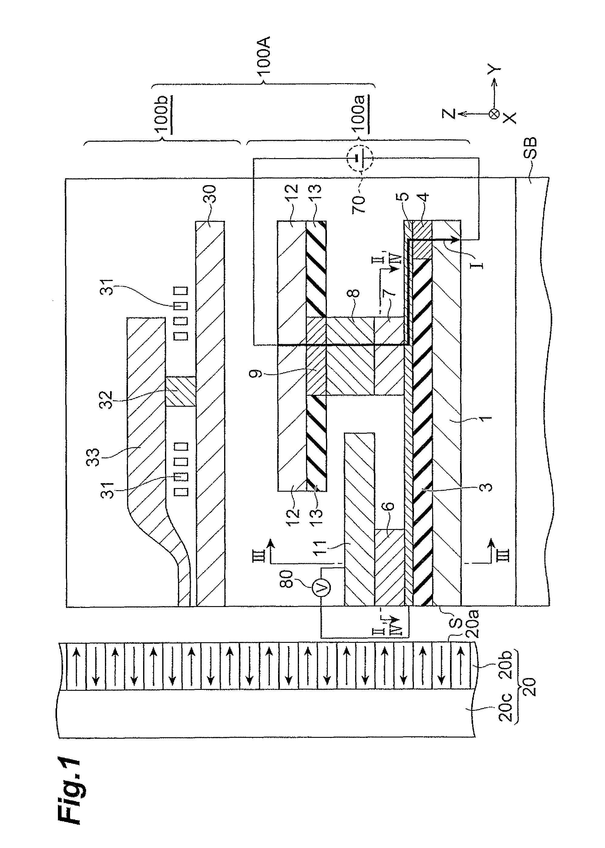
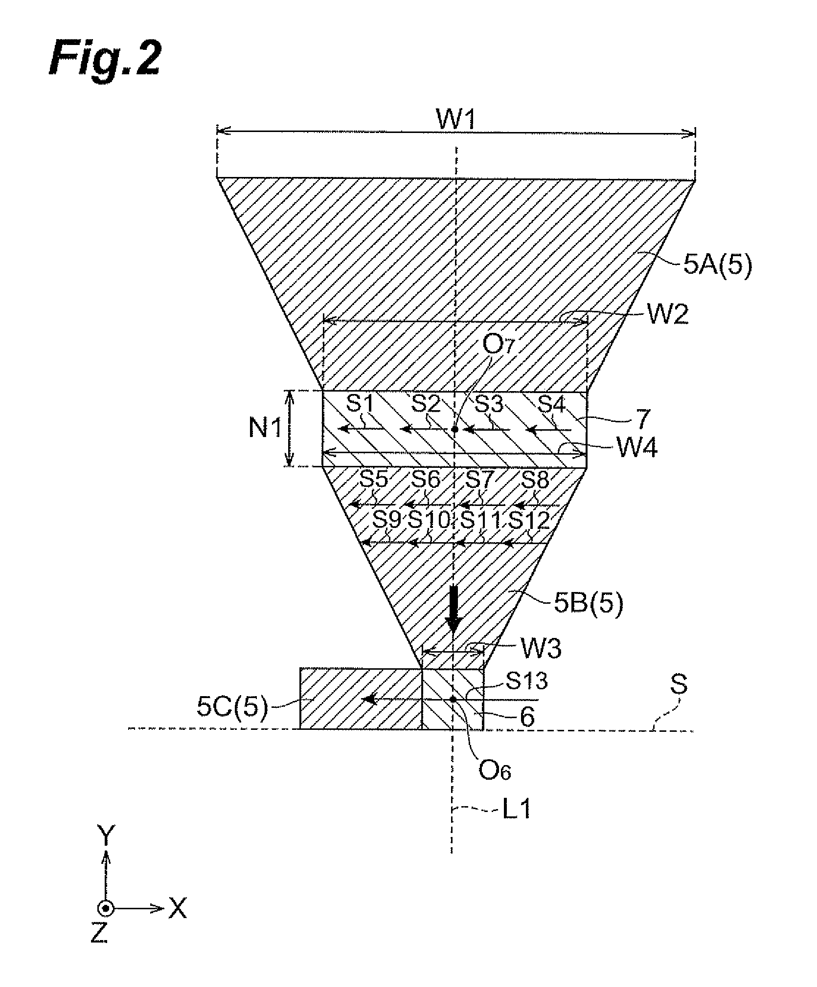
[0032]FIG. 1 is a partial sectional view showing the thin-film magnetic recording / reproducing head 100A. FIG. 2 is a sectional view along line II-II in FIG. 1. FIG. 2 shows a shape of a channel layer without illustration of a third insulating layer 14 and a permanent magnet 15 described later.

[0033]The thin-film magnetic recording / reproducing head 100A performs recording and reading operations of magnetic information at a position where its air bearing surface (surface opposed to a medium) S is arranged opposite to a recording surface 20a of a magnetic recording medium 20. The magnetic recording medium 20 consists of a recording layer 20b having the recording surface 20a, and a soft magnetic backing layer 20c laid on the recording layer 20b, and moves relative to the thin-film magnetic recording / reproducing head 100A in a direction i...

second embodiment

[0077]The magnetic sensor according to the second embodiment will be described below. FIG. 4 is a sectional view along line IV-IV in FIG. 1. In FIG. 4, the shape of the channel layer is depicted without illustration of the aforementioned third insulating layer 14 and permanent magnet 15.

[0078]The magnetic sensor shown in FIG. 4 is different in the shapes of the magnetization fixed layer and the channel layer from the magnetic sensor of the first embodiment, and only these will be described below.

[0079]In the magnetic sensor of the second embodiment, as shown in FIG. 4, when viewed from the thickness direction (Z-axis direction) of the channel layer, the magnetization fixed layer 7C has an arc shape which forms a part of a circle centered on the geometrical centroid O6 of the magnetization free layer 6. Furthermore, when viewed from the thickness direction of the channel layer, the magnetization fixed layer 7C is line-symmetric with respect to a straight line L2 connecting the geomet...


PUM

PropertyMeasurementUnit
external magnetic fieldaaaaaaaaaa
magnetizationaaaaaaaaaa
thicknessaaaaaaaaaa

Abstract

An object is to provide a magnetic sensor permitting an increase in potential output. The magnetic sensor has a channel layer, a magnetization free layer provided on a first portion of the channel layer and configured to detect an external magnetic field, and a magnetization fixed layer provided on a second portion different from the first portion of the channel layer, and a cross-sectional area of the magnetization fixed layer in a surface opposed to the channel layer is larger than a cross-sectional area of the magnetization free layer in a surface opposed to the channel layer.

Description

BACKGROUND OF THE INVENTION[0001]1. Field of the Invention[0002]The present invention relates to a magnetic sensor.[0003]2. Related Background Art[0004]A magnetoresistive element is known as a magnetic sensor used in a thin-film magnetic recording / reproducing head or the like. In the magnetoresistive element, generally, an electric current is made to flow between a magnetization fixed layer and a magnetization free layer, thereby obtaining a high output. However, the magnetoresistive element produces a signal unnecessary for the magnetic sensor, which is caused, for example, by domain wall displacement due to spin torque given by the electric current.[0005]Another known magnetic sensor is a Spin Accumulation (SA) magnetic sensor in which the magnetization free layer and the magnetization fixed layer are formed on an identical horizontal surface (channel layer for spin accumulation) (e.g., cf. Patent Document 1 and Patent Document 2). For example, when the spin accumulation magnetic ...

Claims


Application Information

Patent Timeline
Patent Type & Authority Patents(United States)
IPC IPC(8): G11B5/39
CPCB82Y10/00B82Y25/00G01R33/093G11B5/3906Y10T428/115G11B2005/3996H01F10/3254Y10T428/11
Inventor SASAKI, TOMOYUKI
Owner TDK CORPARATION
Why Eureka
Try Eureka