Fluid machine and refrigeration cycle apparatus

a cycle apparatus and flue gas technology, applied in the field of flue gas machine and cycle apparatus, can solve the problems of insufficient water heating, reducing the temperature of stored hot water to a lower than the preset one, and raising the temperature of discharged refrigerant by reducing the temperature of refrigerant somewhat excessively, so as to suppress the heat transfer from the surrounding space, increase the thermal resistance of the cylinder, and reduce the effect of the cylinder's surrounding spa

Inactive Publication Date: 2012-01-03
PANASONIC CORP
View PDF17 Cites 24 Cited by
  • Summary
  • Abstract
  • Description
  • Claims
  • Application Information

AI Technical Summary

Benefits of technology

[0011]It is an object of the present invention to provide a fluid machine capable of reducing an amount of oil discharged to (an amount of oil circulating through) a cycle and of suppressing heat transfer from a compression mechanism to an expansion mechanism without increasing mechanical loss.
[0015]In the above-mentioned fluid machine of the first aspect of the present invention, the working fluid that has been guided to the through-hole of the cylinder through the suction pipe flows through the through-hole from the first side to the second side of the axis direction and thereafter is drawn into the expansion chamber through the suction port. The through-hole is provided between the expansion chamber and the outer circumferential surface of the cylinder. The thermal resistance of the cylinder is increased by providing the through-hole around the expansion chamber, compared with the case without providing any through-hole. Therefore, the heat transfer from the surrounding space of the cylinder to the expansion chamber is suppressed. In other words, the heat transfer from the compression mechanism to the expansion mechanism is suppressed.
[0016]The high-temperature and high-pressure working fluid is discharged into the internal space of the closed casing, and thus the surrounding space of the expansion mechanism also is in a high-pressure atmosphere. Therefore, if the through-hole is a simple hollow cavity, a concern about the withstanding pressure of the cylinder might arise. In contrast, in the present invention, the low-temperature and high-pressure working fluid to be expanded flows through the through-hole. Therefore, the present invention has no such problem of the cylinder being deformed by the external pressure. In addition, since the flow passage area of the through-hole is larger than that of the suction pipe, the flow speed of the working fluid is reduced in the through-hole. As a result, the heat transfer coefficient on a working fluid side part where the through-hole is provided decreases, and thus the effect of suppressing the heat transfer is enhanced further.
[0017]Furthermore, the working fluid to be expanded receives heat in the process of flowing through the through-hole and raises its temperature. Therefore, the mechanical power to be recovered theoretically in the expansion process increases, which increases the absolute value of the recoverable mechanical power by the expansion mechanism. In other words, when the fluid machine of the present invention is used for a refrigeration cycle apparatus, the performance of the refrigeration cycle can be enhanced.
[0020]According to the fluid machine of the second aspect of the present invention, the cylinder is provided with a plurality of through-holes. The working fluid that has been guided from the suction pipe to the through-holes by way of the branching passage is merged in the merging passage after flowing through the through-holes from the first side to the second side and drawn into the expansion chamber. The thermal resistance of the cylinder is increased by providing the plurality of through-holes around the expansion chamber, compared with the case without providing any through-hole. Therefore, the heat transfer from the surrounding space of the cylinder to the expansion chamber is suppressed. In this case, there is no limitation on the size relationship between the flow passage area of the suction pipe and that of the through-holes.
[0021]According to the fluid machine of the third aspect of the present invention, the jacket disposed around the expansion mechanism forms, around the expansion mechanism, a space through which a working fluid to be drawn into the expansion mechanism passes. The thermal resistance of this space through which the working fluid to be expanded passes is higher than that of the components of the expansion mechanism. Accordingly, the effect of suppressing the heat transfer from the surrounding space of the expansion mechanism to the expansion chamber, that is, the effect of suppressing the heat transfer from the compression mechanism to the expansion mechanism is obtained.

Problems solved by technology

However, when a thermal short-circuit occurs between the compression mechanism and the expansion mechanism, the temperature of the refrigerant discharged from the compression mechanism drops, which causes insufficient heating of water and thus reduces the temperature of the stored hot water to a temperature lower than the preset one.
Specifically, the temperature of the discharged refrigerant is raised by compressing the refrigerant somewhat excessively.
This method, however, imposes an excessive workload on the compression mechanism.
Therefore, the power consumption of the motor increases, which reduces the effect of recovering mechanical power in the expansion mechanism.
The discharged oil adheres to a refrigerant pipe and increases pressure loss, or degrades the performance of the radiator and the evaporator.
In this case, a mechanical seal must be used to prevent the leakage of the refrigerant from a clearance between the shaft 605 and the partitioning member 650, which causes a concern about an increase in friction loss.

Method used


Image

  • Fluid machine and refrigeration cycle apparatus
  • Fluid machine and refrigeration cycle apparatus
  • Fluid machine and refrigeration cycle apparatus

Examples


first embodiment

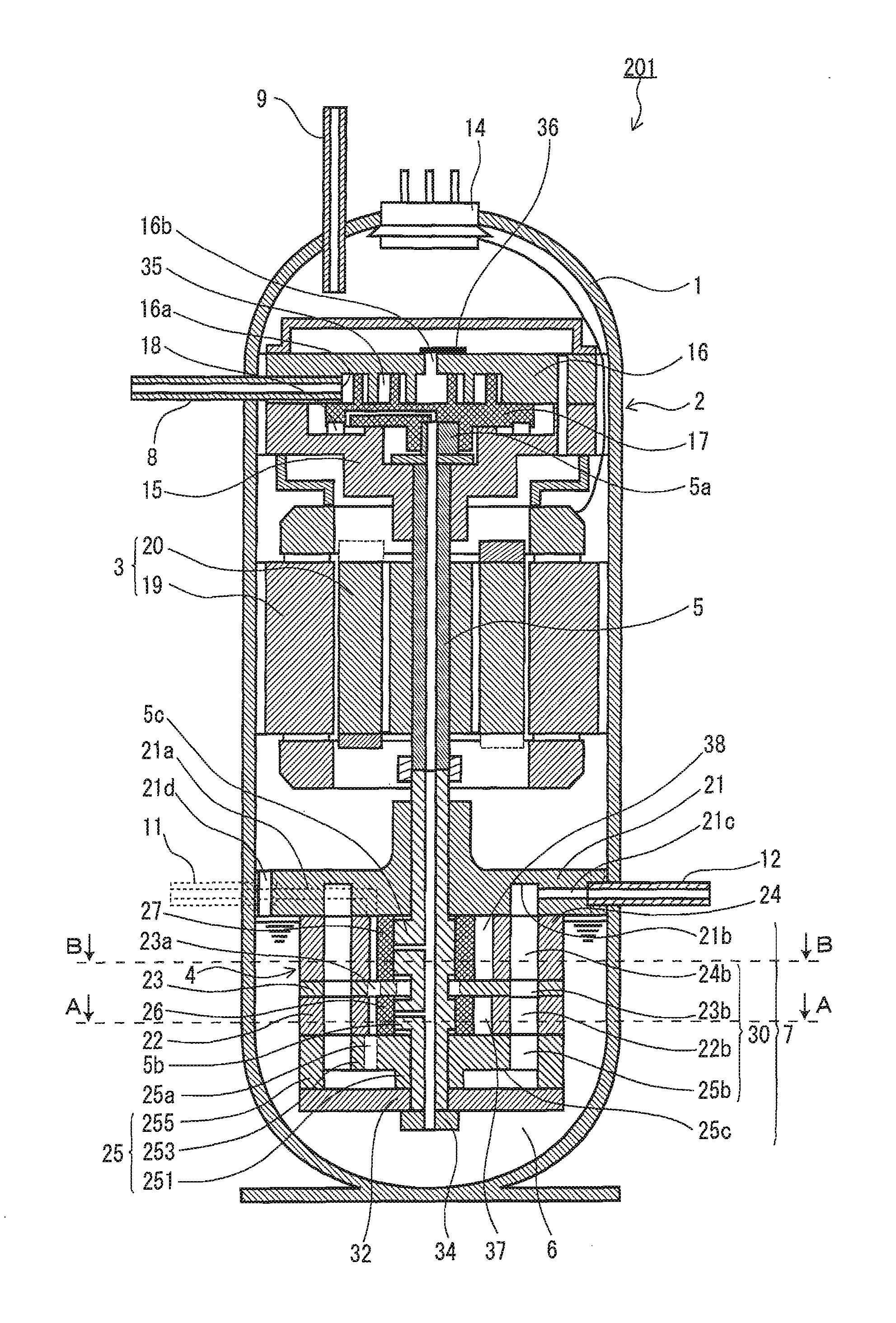
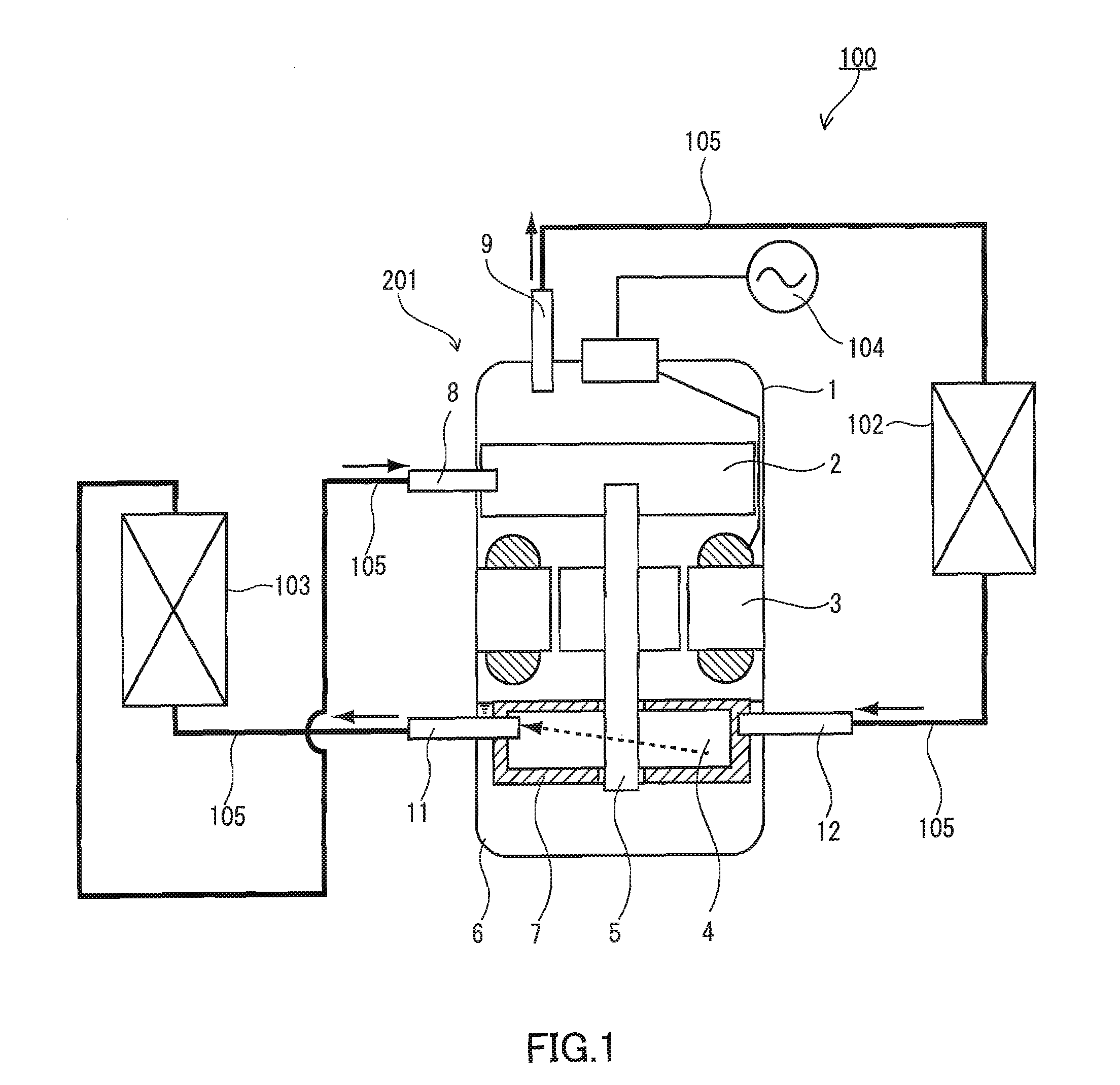
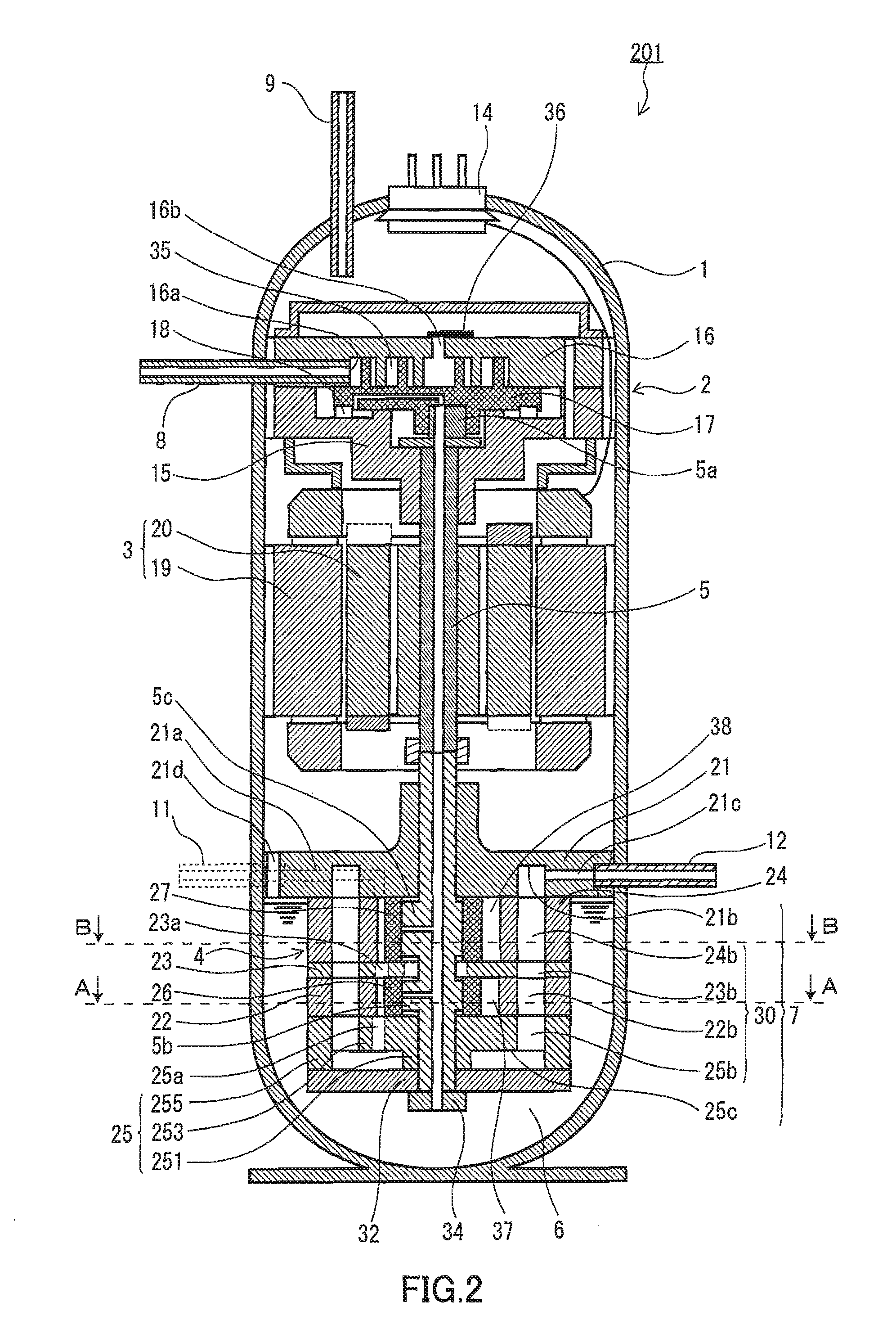
[0035]FIG. 1 is a configuration diagram illustrating a refrigeration cycle apparatus according to an embodiment of the present invention. FIG. 2 is a vertical sectional view of a fluid machine applied to the refrigeration cycle apparatus shown in FIG. 1. FIG. 3A is a cross-sectional view of the fluid machine taken along the line B-B of FIG. 2. FIG. 3B is a cross-sectional view thereof taken along the line A-A of FIG. 2.

[0036]As shown in FIG. 1, a refrigeration cycle apparatus 100 includes a fluid machine 201 (expander-integrated compressor), a radiator 102, an evaporator 103, and a plurality of refrigerant pipes for connecting the fluid machine 201, the radiator 102, and the evaporator 103 so as to form a main refrigerant circuit through which a refrigerant circulates. The refrigerant as a working fluid is, for example, carbon dioxide or hydrofluorocarbon.

[0037]The fluid machine 201 includes a compression mechanism 2 for compressing the refrigerant, a motor 3, an expansion mechanism...

second embodiment

[0071]FIG. 5 is a vertical sectional view of another fluid machine that can be used suitably for the refrigeration cycle apparatus100 of FIG. 1. As shown in FIG. 5, the basic configuration of a fluid machine 202 of the present embodiment is the same as that of the fluid machine described in the first embodiment.

[0072]The present embodiment differs from the above-described first embodiment in the form of the refrigerant passage space 7. In the present embodiment, the refrigerant passage space 7 through which a refrigerant to be drawn into an expansion mechanism 40 passes is formed of a jacket disposed around the expansion mechanism 40. One example of such a jacket is a pipe 39 wound around the expansion mechanism 40. The internal space of the pipe is used as the refrigerant passage space 7. According to the present embodiment, since the pipe merely is wound around the expansion mechanism 40, its cost is low. As this pipe 39, an inner grooved pipe for a heat exchanger can be used suit...

third embodiment

[0077]FIG. 6 is a vertical sectional view of another fluid machine that can be used suitably for the refrigeration cycle apparatus 100 of FIG. 1. As shown in FIG. 6, the basic configuration of a fluid machine 203 of the present embodiment is the same as that of the fluid machine described in the first embodiment.

[0078]The expansion mechanism 40 in the fluid machine 203 of the present embodiment is a rotary expansion mechanism including: rollers 26, 27 mounted on the shaft 5; cylinders 22, 24 in which the rollers 26, 27 are disposed; and a suction pipe 12 for guiding a refrigerant to be expanded to the expansion mechanism4. The basic configuration of the rotary expansion mechanism is the same as described in the first embodiment.

[0079]As described in the second embodiment, the refrigerant passage space 7 through which the refrigerant to be drawn into the expansion mechanism 40 passes is formed of a jacket disposed around the expansion mechanism 40. In the present embodiment, such a j...


PUM


Abstract

A fluid machine (201) includes: a compression mechanism (2) for compressing a working fluid; an expansion mechanism (4) for expanding the working fluid and for recovering mechanical power from the expanding working fluid; a shaft (5) for coupling the compression mechanism (2) and the expansion mechanism (4) and for transferring the mechanical power recovered by the expansion mechanism (4) to the compression mechanism (2); and a closed casing (1) for accommodating the compression mechanism (2), the shaft (5) and the expansion mechanism (4), and having an internal space into which the working fluid that has been compressed by the compression mechanism (2) is discharged. A refrigerant passage space (7) through which a refrigerant to be drawn into the expansion mechanism (4) passes is formed between an expansion chamber of the expansion mechanism (4) and the internal space of the closed casing (1).

Description

TECHNICAL FIELD[0001]The present invention relates to a refrigeration cycle apparatus to be applied to a refrigerating air conditioner, a water heater, and the like, and further relates to a fluid machine that can be used suitably for a refrigeration cycle apparatus.BACKGROUND ART[0002]As a fluid machine constituting a refrigeration cycle apparatus, a fluid machine 419, as shown in FIG. 7, in which a compression mechanism 402 for compressing a refrigerant and an expansion mechanism 404 for converting expansion energy of a refrigerant with its decompression and expansion into mechanical power are integrated as a single unit, has been known (JP 62(1987)-77562 A). By supplying the mechanical power obtained by the expansion mechanism 404 to the compression mechanism 402 by a shaft 405, the efficiency of the refrigeration cycle apparatus is enhanced.[0003]Since the compression mechanism 402 compresses the refrigerant adiabatically, the temperature of the components of the compression mec...

Claims


Application Information

Patent Timeline
Patent Type & Authority Patents(United States)
IPC IPC(8): F25D9/00
CPCF01C1/3442F01C11/004F01C11/008F04C18/0215F04C23/008
Inventor OGATA, TAKESHIHIKICHI, TAKUMIOKAICHI, ATSUOMATSUI, MASARUHASEGAWA, HIROSHI
Owner PANASONIC CORP
Why Eureka
Try Eureka