Fluid machine and refrigeration cycle apparatus
- Summary
- Abstract
- Description
- Claims
- Application Information
AI Technical Summary
Benefits of technology
Problems solved by technology
Method used
Image
Examples
first embodiment
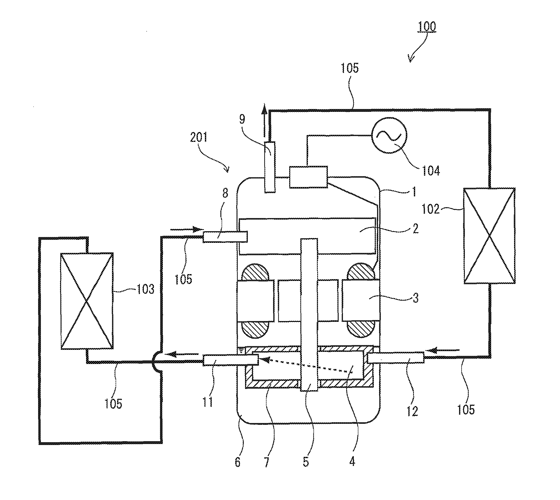
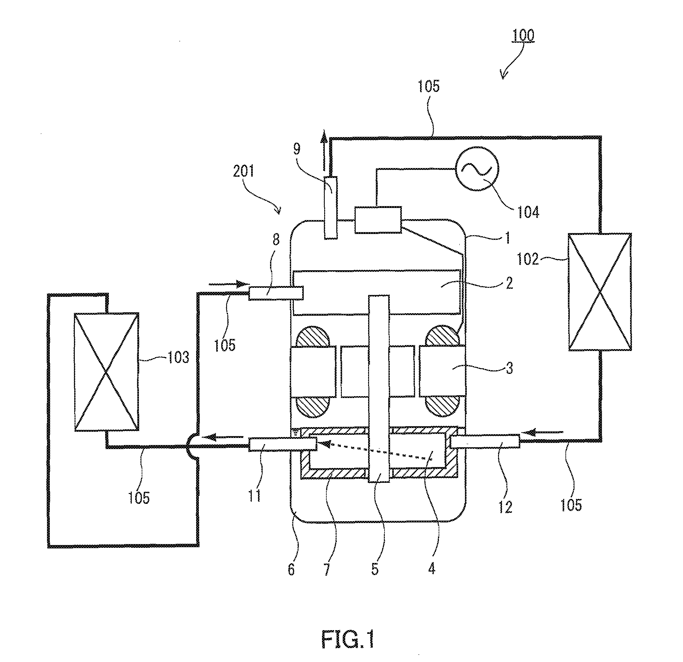
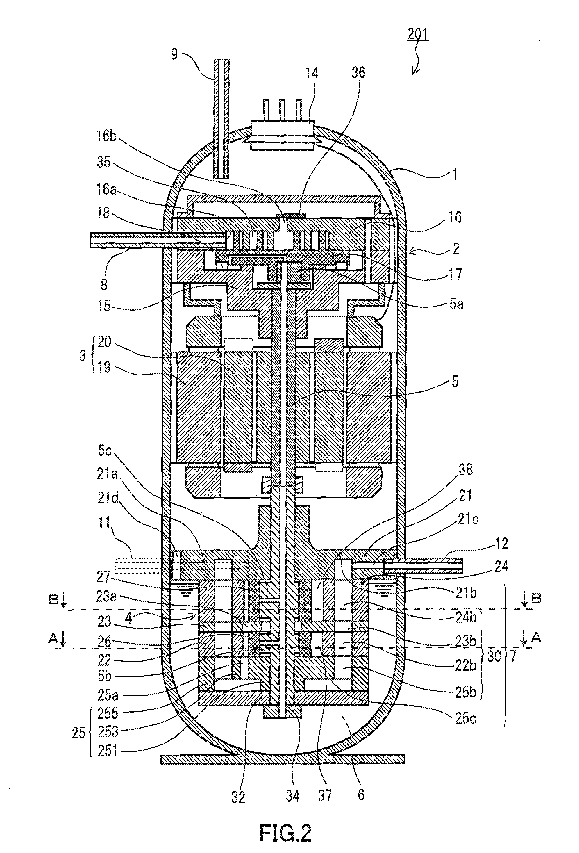
[0035]FIG. 1 is a configuration diagram illustrating a refrigeration cycle apparatus according to an embodiment of the present invention. FIG. 2 is a vertical sectional view of a fluid machine applied to the refrigeration cycle apparatus shown in FIG. 1. FIG. 3A is a cross-sectional view of the fluid machine taken along the line B-B of FIG. 2. FIG. 3B is a cross-sectional view thereof taken along the line A-A of FIG. 2.
[0036]As shown in FIG. 1, a refrigeration cycle apparatus 100 includes a fluid machine 201 (expander-integrated compressor), a radiator 102, an evaporator 103, and a plurality of refrigerant pipes for connecting the fluid machine 201, the radiator 102, and the evaporator 103 so as to form a main refrigerant circuit through which a refrigerant circulates. The refrigerant as a working fluid is, for example, carbon dioxide or hydrofluorocarbon.
[0037]The fluid machine 201 includes a compression mechanism 2 for compressing the refrigerant, a motor 3, an expansion mechanism...
second embodiment
[0071]FIG. 5 is a vertical sectional view of another fluid machine that can be used suitably for the refrigeration cycle apparatus 100 of FIG. 1. As shown in FIG. 5, the basic configuration of a fluid machine 202 of the present embodiment is the same as that of the fluid machine described in the first embodiment.
[0072]The present embodiment differs from the above-described first embodiment in the form of the refrigerant passage space 7. In the present embodiment, the refrigerant passage space 7 through which a refrigerant to be drawn into an expansion mechanism 40 passes is formed of a jacket disposed around the expansion mechanism 40. One example of such a jacket is a pipe 39 wound around the expansion mechanism 40. The internal space of the pipe is used as the refrigerant passage space 7. According to the present embodiment, since the pipe merely is wound around the expansion mechanism 40, its cost is low. As this pipe 39, an inner grooved pipe for a heat exchanger can be used sui...
third embodiment
[0077]FIG. 6 is a vertical sectional view of another fluid machine that can be used suitably for the refrigeration cycle apparatus 100 of FIG. 1. As shown in FIG. 6, the basic configuration of a fluid machine 203 of the present embodiment is the same as that of the fluid machine described in the first embodiment.
[0078]The expansion mechanism 40 in the fluid machine 203 of the present embodiment is a rotary expansion mechanism including: rollers 26, 27 mounted on the shaft 5; cylinders 22, 24 in which the rollers 26, 27 are disposed; and a suction pipe 12 for guiding a refrigerant to be expanded to the expansion mechanism 4. The basic configuration of the rotary expansion mechanism is the same as described in the first embodiment.
[0079]As described in the second embodiment, the refrigerant passage space 7 through which the refrigerant to be drawn into the expansion mechanism 40 passes is formed of a jacket disposed around the expansion mechanism 40. In the present embodiment, such a ...
PUM
 Abstract
Description
Claims
Application Information
 - R&D
- Intellectual Property
- Life Sciences
- Materials
- Tech Scout
- Unparalleled Data Quality
- Higher Quality Content
- 60% Fewer Hallucinations
Browse by: Latest US Patents, China's latest patents, Technical Efficacy Thesaurus, Application Domain, Technology Topic, Popular Technical Reports.
© 2025 PatSnap. All rights reserved.Legal|Privacy policy|Modern Slavery Act Transparency Statement|Sitemap|About US| Contact US: help@patsnap.com


