
Expander-compressor unit and refrigeration cycle apparatus having the same

a compressor unit and compressor technology, applied in the direction of positive displacement liquid engine, lighting and heating apparatus, piston pump, etc., can solve the problems of reducing increasing the power consumption of the motor, and deteriorating the capacity of the radiator and the evaporator, so as to reduce the heat transfer, improve the efficiency of the refrigeration cycle apparatus, and suppress the discharge

Inactive Publication Date: 2010-07-01
PANASONIC CORP
View PDF7 Cites 13 Cited by
  • Summary
  • Abstract
  • Description
  • Claims
  • Application Information

AI Technical Summary

Benefits of technology

[0013]In view of the foregoing, the present invention is intended to provide an expander-compressor unit that can suppress a discharge amount of oil, and can reduce the heat transfer between the compression mechanism and the expansion mechanism without increasing mechanical loss.
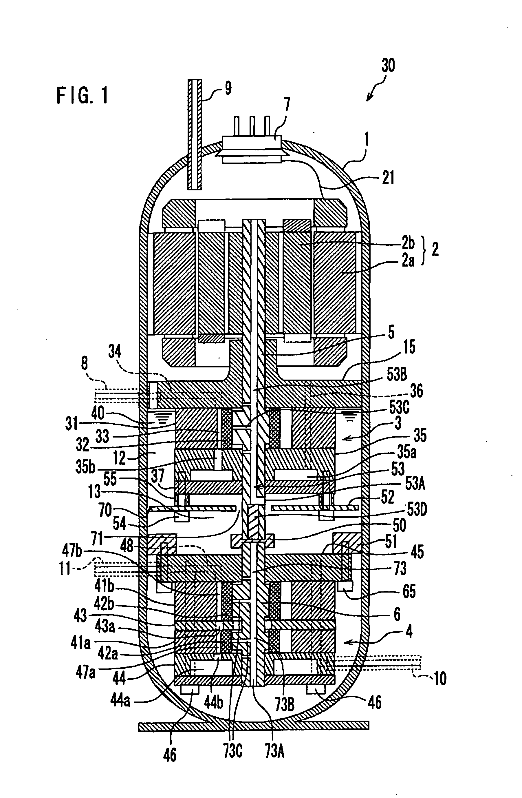
[0015]In the expander-compressor unit of the present invention, the motor, the compression mechanism, and the expansion mechanism are disposed from top to bottom in the closed casing in descending order of temperature. As a result, a stratified temperature-distribution is formed in the refrigerant and the oil based on the temperature gradient in the closed casing. This makes it possible to reduce heat transfer caused by convection of the refrigerant and the oil in the closed casing.
[0016]The oil suction portion of the oil supply passage for supplying the oil to the compression mechanism is disposed at a position above the expansion mechanism. Thus, the relatively high temperature oil present higher than the expansion mechanism is supplied to the compression mechanism, and the relatively low temperature oil present lower than the oil suction portion is supplied to the expansion mechanism. This enables circulation of the high temperature oil, which lubricates the compression mechanism, above the expansion mechanism, and can prevent the expansion mechanism from receiving heat from the high temperature oil. As a result, the heat transfer between the compression mechanism and the expansion mechanism via the oil is suppressed, improving efficiency of the refrigeration cycle apparatus.
[0017]The expander-compressor unit of the present invention is a so-called high pressure shell type expander-compressor unit in which the discharge refrigerant from the compression mechanism is once released into an internal space of the closed casing, and then is discharged out of the closed casing. Accordingly, the expander-compressor unit of the present invention can separate sufficiently the oil from the discharge refrigerant from the compression mechanism, and thereby has no possibility of having oil shortage.
[0018]Moreover, unlike in the conventional example (see FIG. 11) in which the interior of the closed casing is partitioned into the high pressure side space and the low pressure side space, the expander-compressor unit of the present invention does not require a special structure around the shaft, such as the mechanical seal for preventing the refrigerant leakage between the high pressure side space and the low pressure side space. Therefore, there arises no problem of an increased mechanical loss of the shaft resulting from the mechanical seal, either.
[0019]As described above, the present invention can suppress the discharge amount of oil as well as reduce the heat transfer between the compression mechanism and the expansion mechanism without increasing the mechanical loss.

Problems solved by technology

The deteriorations in the capacities of the radiator and the evaporator are not preferable because they mean a decrease in the efficiency of the refrigeration cycle apparatus.
However, this method makes the compression mechanism 402 perform excessive work, increasing the power consumption at a motor.
However, such a configuration increases the cost for the heat insulating material 504.
The discharged oil adheres to a refrigerant pipe and increases pressure loss of the refrigerant, as well as deteriorates the capacities of the radiator and the evaporator, exerting an adverse effect on the performance of the refrigeration cycle apparatus.
However, JP 2003-139059 A does not disclose detailed configuration of each layout.

Method used


Image

  • Expander-compressor unit and refrigeration cycle apparatus having the same
  • Expander-compressor unit and refrigeration cycle apparatus having the same
  • Expander-compressor unit and refrigeration cycle apparatus having the same

Examples


embodiment 1

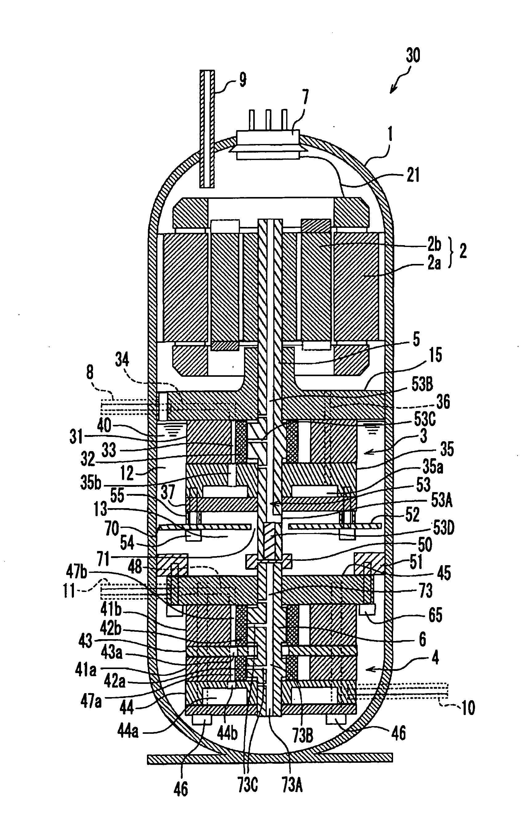
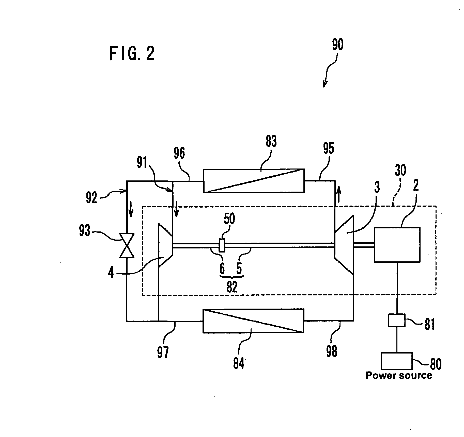
[0033]FIG. 1 is a vertical cross-sectional view of an expander-compressor unit 30 according to Embodiment 1 of the present invention. FIG. 2 shows a refrigeration cycle apparatus 90 having the expander-compressor unit 30.

[0034]As shown in FIG. 1, the expander-compressor unit 30 includes a motor 2 operating in response to electric power supply from a commercial power source 80 (see FIG. 2), a compression mechanism 3 for compressing a refrigerant, an expansion mechanism 4 for allowing the refrigerant to expand, and a closed casing 1 accommodating these elements 2, 3, and 4. The motor 2, the compression mechanism 3, and the expansion mechanism 4 are disposed in this order from top to bottom. An oil 40 for lubricating the sliding parts of the compression mechanism 3 and the expansion mechanism 4 is held at a bottom portion of the closed casing 1 (it should be noted that the “bottom portion” here means a lower side with respect to an arbitrary predetermined position, and does not necessa...

embodiment 2

[0067]FIG. 3 is a vertical cross-sectional view of the expander-compressor unit 30 according to Embodiment 2 of the present invention. As shown in FIG. 3, the expander-compressor unit 30 of the present embodiment has almost the same configuration as that of the expander-compressor unit described in Embodiment 1 (see FIG. 1). Hereinbelow, components having the same functions are indicated by the same reference numerals, and explanations thereof are omitted.

[0068]A difference between the present embodiment and Embodiment 1 is the shape of the flow suppressing plate 62. The flow suppressing plate 62 of the present embodiment is a cut-out plate of an approximately annular shape having cut-outs 62a in an outer peripheral portion thereof. The cut-outs 62a intermittently are formed along the outer periphery of the flow suppressing plate 62. The number of the cut-outs 62a is not particularly limited. The flow suppressing plate 62 of the present embodiment also has the hole 71 at its center ...

embodiment 3

[0072]FIG. 4 is a vertical cross-sectional view of the expander-compressor unit 30 according to Embodiment 3 of the present invention. As shown in FIG. 4, the expander-compressor unit 30 of the present embodiment has almost the same configuration as that of the expander-compressor unit described in Embodiment 2 (see FIG. 3). Hereinbelow, components having the same functions are indicated by the same reference numerals, and explanations thereof are omitted.

[0073]A difference between the present embodiment and Embodiment 2 is the configuration of the oil supply passage. An oil supply passage 63 of the present embodiment includes oil grooves 63B, 63C and 63D formed in the outer peripheral surface of the compression mechanism side shaft 5, and continuous passages (not shown) bringing them into communication with each other. The oil grooves 63B and 63D are formed in the outer peripheral surface of the compression mechanism side shaft 5, at a portion higher than an eccentric portion of th...


PUM


Abstract

An expander-compressor unit (30) includes: a closed casing (1) holding an oil at a bottom portion thereof; a motor (2) provided in the closed casing (1); a compression mechanism (3) for compressing a refrigerant and discharging it into the closed casing (1), the compression mechanism (3) being disposed below the motor (2) in the closed casing (1); an expansion mechanism (4) disposed below the compression mechanism (3) in the closed casing (1); and a coupling mechanism (50) for coupling a compression mechanism side shaft (5) to an expansion mechanism side shaft (6). An oil supply passage (53) for supplying the oil to the compression mechanism (3) is formed in the compression mechanism side shaft (5). An oil suction port (53A) is provided in a portion of the compression mechanism side shaft (5), the portion being above the expansion mechanism (4).

Description

TECHNICAL FIELD[0001]The present invention relates to an expander-compressor unit applied to a refrigeration cycle apparatuses, such as a refrigerator, an air conditioner, and a water heater, and also relates to a refrigeration cycle apparatus having the expander-compressor unit.BACKGROUND ART[0002]As a fluid machine forming a part of a refrigeration cycle apparatus, an expander-compressor unit 400 is known that is constituted by integrating a compression mechanism 402 for compressing a refrigerant with an expansion mechanism 404 for allowing a refrigerant to expand and converting into mechanical energy the expansion energy generated during the refrigerant is expanded and decompressed, as shown in FIG. 6 (see JP 62(1987)-77562 A). In the expander-compressor unit 400, the mechanical energy resulted from the conversion by the expansion mechanism 404 is utilized as a part of energy for rotating a shaft 405 of the compression mechanism 402. This reduces input to the compression mechanis...

Claims


Application Information

Patent Timeline
IPC IPC(8): F25B1/00F04B25/00F04B35/04
CPCF01C1/3564F01C11/004F01C21/04F04C18/3564F04C23/008F04C29/023
Inventor OKAICHI, ATSUOTAKAHASHI, YASUFUMIHASEGAWA, HIROSHIMATSUI, MASARUSAKIMA, FUMINORI
Owner PANASONIC CORP
Learn More