Firearm suppressor with slip and capacitance chambers

a technology of capacitance chamber and firearm, which is applied in the direction of muzzle attachment, weapon components, weapons, etc., can solve the problem that the art system lacks a robust embodiment of frame members

Inactive Publication Date: 2012-01-03
DARITECH
View PDF28 Cites 65 Cited by
  • Summary
  • Abstract
  • Description
  • Claims
  • Application Information

AI Technical Summary

Problems solved by technology

Such embodiments are not only difficult to clean and maintain but further provide a great deal of surface area which may have difficulty withstanding the highly eroding nature of the high pressure and very hot gases.
However, the prior art systems lack a robust embodiment of having a frame member with inserts configured to fit therein that are designed to properly direct and absorb the kinetic energy of the expanding gases and have a lifespan of a sufficient number of rounds passing therethrough.

Method used


Image

  • Firearm suppressor with slip and capacitance chambers
  • Firearm suppressor with slip and capacitance chambers
  • Firearm suppressor with slip and capacitance chambers

Examples


Embodiment Construction

[0027]With the foregoing general description in place, there will now be a more detailed discussion of the various embodiments showing the sound suppressor device concept.

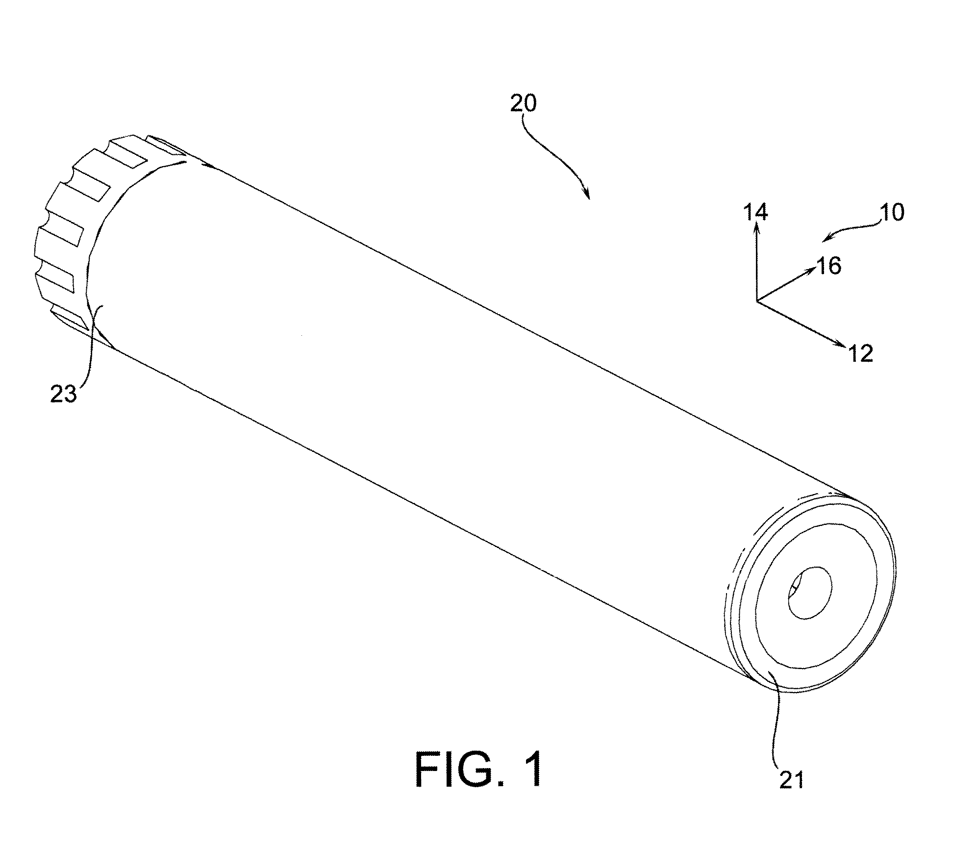
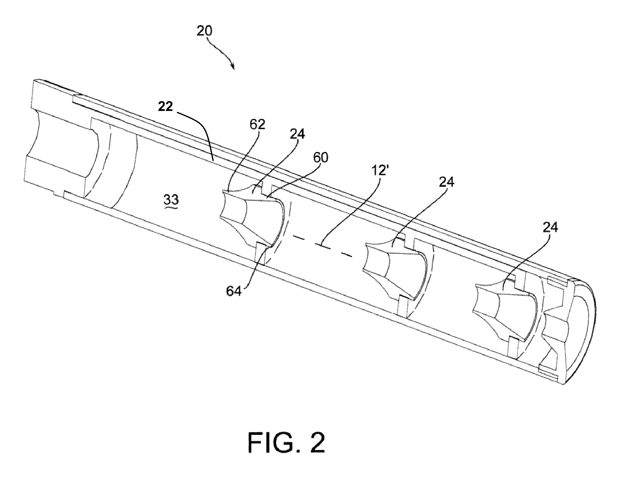
[0028]FIG. 1 shows a sound suppressor device 20 generally having a forward region 21 and a longitudinal rearward region 23. As shown in FIG. 1, an axes system 10 is defined where the axis 12 indicates a longitudinal axis and the axes 14 and 16 respectively define a vertical and lateral axis, wherein each of these directions point radially outwardly from the central longitudinal axis 12′ as shown in FIG. 2.

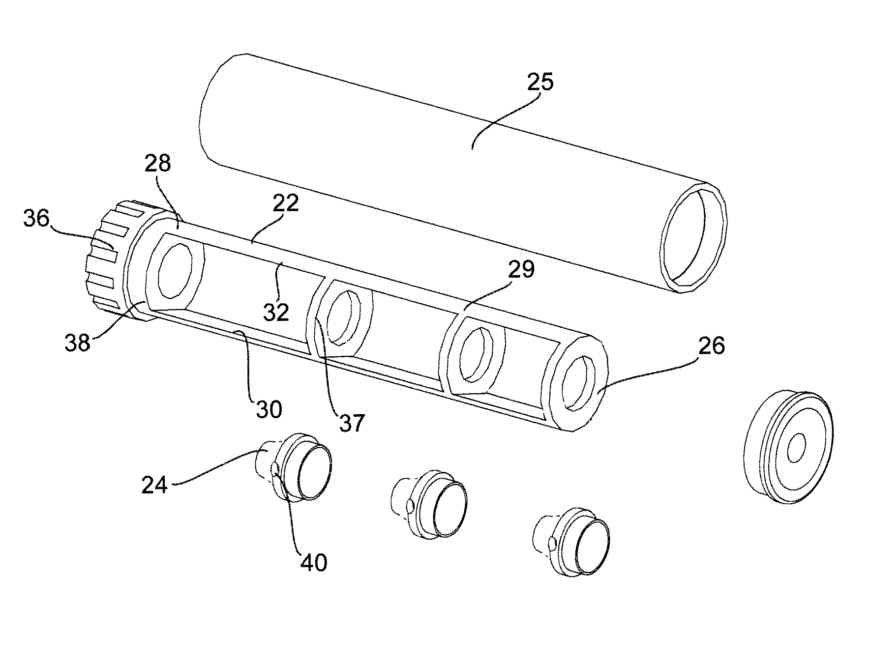
[0029]As shown in FIG. 2 there is a cross-sectional isometric view of a sound suppressor device 20. In general, the suppressor device 20 comprises a base frame 22 and a plurality of inserts 24.

[0030]The base frame 22 itself generally comprises a longitudinally forward region 26 and a longitudinally rearward region 28 as shown in FIG. 3. The frame 22 has a plurality of cross bar regions 37 which are operatively con...


PUM


Abstract

A firearm noise suppressor having an internal base frame member with a plurality of inserts mounted thereto. In one form the suppressor is provided with a slip chamber allowing gas to be forwarded to a longitudinally forward chamber for pre-compression of gas therein.

Description

RELATED APPLICATIONS[0001]This application claims priority benefit of U.S. Ser. No. 61 / 025,450, filed Feb. 1, 2008.BACKGROUND OF THE DISCLOSURE[0002]Suppressors have been utilized with firearms to reduce the noise from the expanding gases expelled from the muzzle region of a barrel. In general, the operational element of a suppressor is to absorb / properly direct the kinetic energy of the expanding gases. Many prior art types of suppressors utilized a plurality of passageways such as a steel wool like arrangement. Such embodiments are not only difficult to clean and maintain but further provide a great deal of surface area which may have difficulty withstanding the highly eroding nature of the high pressure and very hot gases.[0003]Other prior art references utilize a unitary type structure of a single piece of metal to form chambers. However, the prior art systems lack a robust embodiment of having a frame member with inserts configured to fit therein that are designed to properly d...

Claims


Application Information

Patent Timeline
Patent Type & Authority Patents(United States)
IPC IPC(8): F41A21/00
CPCF41A21/36F41A21/30
Inventor HINES, TOM
Owner DARITECH
Why Eureka
Try Eureka