
Cervical intervertebral prosthesis

a cervical and intervertebral technology, applied in the field of cervical intervertebral prosthesis, can solve the problems of cervical prosthesis parts coming loose from one another,

Inactive Publication Date: 2012-01-03
CERVITECH INC
View PDF23 Cites 15 Cited by
  • Summary
  • Abstract
  • Description
  • Claims
  • Application Information

AI Technical Summary

Benefits of technology

[0005]The positioning of the convex hinge surface inside the recess serves not only to secure the hinge core on the connection plate holding it, but also to reduce the overall height of the prosthesis. The radius of the convex hinge surface is so small in relation to the cross section of the hinge core that it lies for the most part inside that part of the hinge core surrounded by the recess of the lower connection plate. The hinge core can be configured such that it lies almost exclusively inside the recess. However, it can be provided with a collar which rests on the top face of the edge of the recess in order to rule out direct contact between the metal parts of the upper and lower connection plates upon flexion of the joint.

Problems solved by technology

However, this entails the risk that, if the ligaments connecting the relevant vertebral bodies to one another are too weak or stretched, the prosthesis parts may come loose from one another.
Although it is known (U.S. Pat. No. 5,895,428) to connect the prosthesis parts to one another by means of a screw passing centrally through the hinge surfaces, this cannot be done in conjunction with the abovementioned translatory freedom of movement of the hinge core parallel to the extension of the connection plates, and, in any case, this is impossible in a cervical prosthesis, because of the confined space.

Method used


Image

  • Cervical intervertebral prosthesis
  • Cervical intervertebral prosthesis

Examples


Embodiment Construction

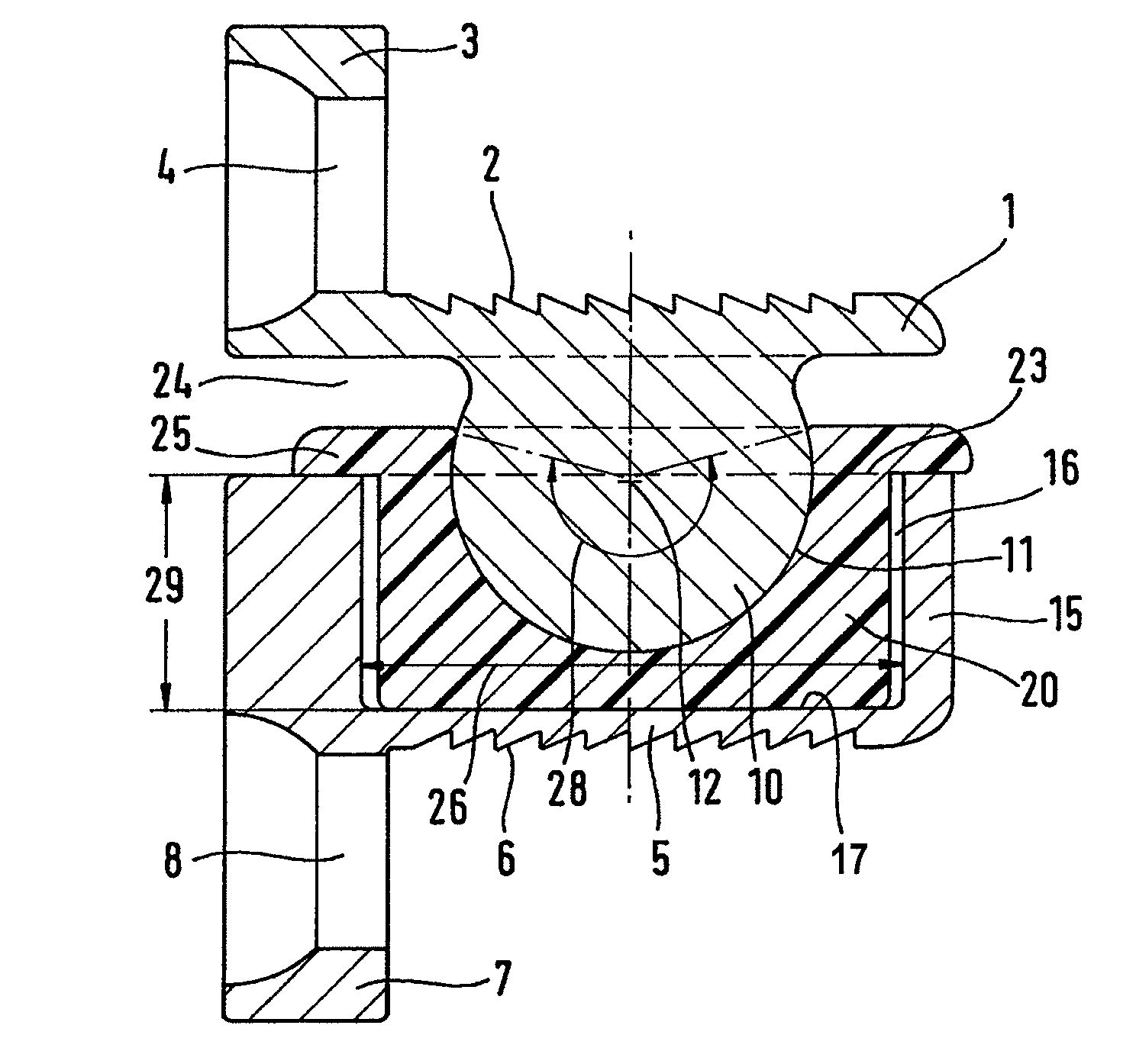
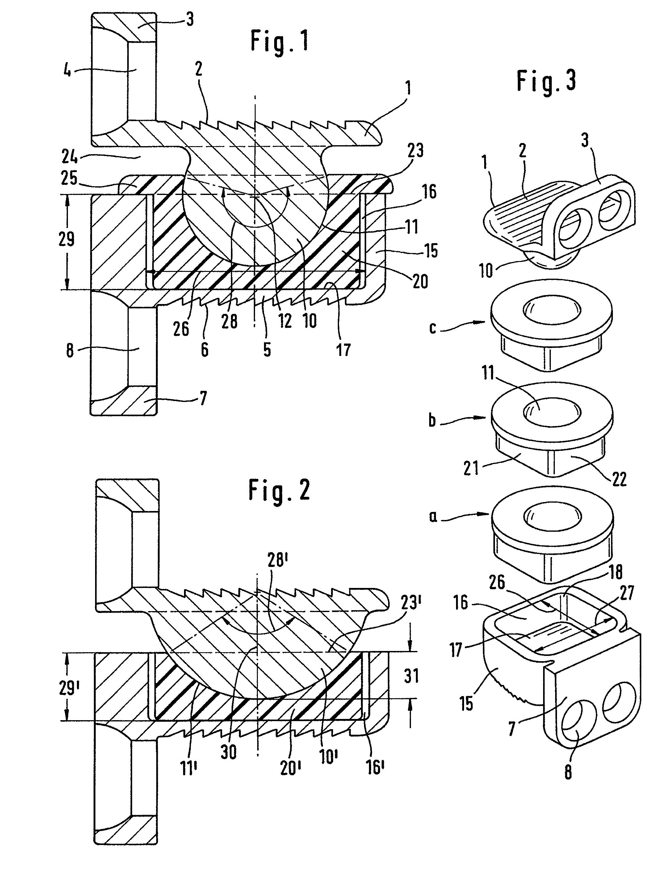
[0012]A first connection plate 1 has a surface 2 intended for connection to the cover plate of a first vertebral body. It can be equipped with teeth or other means permitting intimate connection with the bone tissue. A ventral flange 3 includes a screw bore 4 for a bone screw. It will be appreciated that these structural details of the prosthesis will be able to be configured differently. A second cover plate 5 has a surface 6 for connection to the second vertebral body, and a ventral flange 7 with screw bore 8. The first connection plate 1 is depicted at the top, and it is also in most cases used at the top. In the following, therefore, it is designated as the upper connection plate, and the other one is designated as the lower connection plate. The arrangement, however, can also be the other way round.

[0013]The underside of the upper connection plate carries a hinge head 10 which forms a convex hinge surface 11 with center point 12. The lower connection plate 5 carries a periphera...


PUM


Abstract

A cervical intervertebral prosthesis includes two connection plates adapted for connection to adjacent vertebral bodies and a hinge core. The hinge core and one connection plate together form a hinge with a concave hinge surface on the hinge core and with a complementary convex hinge surface on the connection plate. The hinge core bears on the other connection plate via a slide surface which extends substantially parallel to the direction of the connection plate and which permits a relative movement in this direction and is surrounded by an edge limiting this relative movement. The concave hinge surface encloses the convex hinge surface within a solid angle of at least 90°. The part of the concave hinge surface lying within this solid angle lies inside the recess surrounded by the edge. The stability of the prosthesis with respect to laterally incident forces is thereby increased.

Description

FIELD AND BACKGROUND OF THE INVENTION[0001]A cervical intervertebral prosthesis is known (U.S. Pat. No. 6,368,350) which is composed of an upper connection plate and a lower connection plate for connection to the adjacent vertebral bodies, and of a hinge core which, with one connection plate, forms a hinge with a convex hinge surface on the underside of the upper connection plate and with a concave hinge surface on the top side of the hinge core. The hinge core bears on the other connection plate via a slide surface which extends parallel to the direction of extension of the connection plate and which permits a relative translatory movement of the hinge core in this direction with respect to the lower connection plate. This relative movement is limited by means of the slide surface being restricted by a vertical edge. In the known prosthesis, the hinge surface of the hinge core has a very shallow dish-like configuration. This is customary, because it is possible in this way to achie...

Claims


Application Information

Patent Timeline
Patent Type & Authority Patents(United States)
IPC IPC(8): A61F2/44
CPCA61F2/4425A61F2002/30369A61F2002/305A61F2002/30574A61F2002/30578A61F2002/30604A61F2002/30649A61F2002/30662A61F2002/30904A61F2002/443A61F2220/0025A61F2220/0033A61F2310/00011A61F2310/00179
Inventor KELLER, ARNOLD
Owner CERVITECH INC
Learn More