Radio-frequency tag communication device

a communication device and radio frequency technology, applied in the direction of burglar alarm mechanical actuation, burglar alarm by hand-portable articles removal, etc., can solve the problem of inability to sufficiently prevent the mixing of a direct component in the detected wave, etc. problem, to achieve the effect of increasing the maximum distance of communication, reducing the signal/noise ratio of the received signal, and simple construction

Active Publication Date: 2012-01-03
BROTHER KOGYO KK
View PDF24 Cites 0 Cited by
  • Summary
  • Abstract
  • Description
  • Claims
  • Application Information

AI Technical Summary

Benefits of technology

[0011]The radio-frequency tag communication device of the present invention described above includes the receiver array antenna device consisting of the plurality of antenna elements each provided for receiving the reply signal, the cancel-signal generating portion configured to generate the cancel signal for eliminating the leakage signal that is a part of the transmitted signal, which part is received by the receiver array antenna device, the cancel-signal control portion configured to control the phase and / or the amplitude of the cancel signal generated by the cancel-signal generating portion, and the received-signal combining portion configured to combine together received signals received by the plurality of antenna elements, to obtain a composite signal. The present radio-frequency tag communication device is configured to concurrently control the transmission of the transmitted signal and the reception of the received signals, and to apply the cancel signal generated by the cancel-signal generating portion to the received-signal combining portion, for combining together the received signals and the cancel signal, so that a signal / noise ratio of a wave detector output upon demodulation of the composite signal is improved to increase the maximum distance of communication. Namely, the present invention provides a radio-frequency tag communication device having a receiver portion which is simple in construction and which is capable of sufficiently eliminating the leakage signal received from a transmitter portion.
[0012]Further, unlike a radio-frequency tag communication device wherein the cancel signal is generated for each of a plurality of antenna elements of a receiver array antenna device, the present radio-frequency tag communication device is configured to apply the cancel signal generated by the cancel-signal generating portion, to the received-signal combining portion which combines together the received signals received by the plurality of antenna elements of the receiver array antenna device, so that the present radio-frequency tag communication device does not require a plurality of cancel-signal generating portions, a plurality of cancel-signal control portions and a plurality of cancel-signal combining portions, whereby the receiver portion including the array antenna device can be simplified in construction, but is capable of sufficiently eliminating the leakage signal received from the transmitter portion.
[0013]In addition, the present invention has an advantage of improved accuracy of detection of the direction of reception of an electric wave on the basis of a direction of a main lobe in which the amplitude of the composite signal obtained by the received-signal combining portion is maximum. Accordingly, the direction in which the radio-frequency tag exists can be accurately detected on the basis of the reply signal transmitted from the radio-frequency tag in response to the transmitted signal.
[0014]Preferably, the radio-frequency tag communication device further comprises a directivity control portion configured to control a directivity of reception of the reply signal. In this case, the maximum distance of communication with the radio-frequency tag can be maximized by controlling the directivity of communication with the radio-frequency tag.
[0015]Preferably, the directivity control portion controls the directivity of reception, by controlling phases of the received signals received by the plurality of antenna elements. In this case, the maximum distance of communication can be maximized by controlling the directivity of reception of the reply signal transmitted from the radio-frequency tag.
[0016]Preferably, the cancel-signal control portion sets an initial value of the phase and / or the amplitude of the cancel signal, on the basis of the directivity of reception of the reply signal controlled by the directivity control portion. In this case, the initial value of the phase and / or the amplitude of the cancel signal can be suitably determined.

Problems solved by technology

Where a receiver antenna device is positioned so as to be able to receive the transmitted signal, a part of the transmitted signal may be received by the receiver antenna device, as a leakage signal of a high strength mixed in a received signal received by the receiver antenna device, giving rise to a problem of a reduced signal / noise ratio of the received signal.
In the prior art techniques indicated above, it is not possible to sufficiently prevent mixing of a direct component in the detected wave, where the leakage signal transmitted from a transmitter portion is included in the received signal.
Accordingly, the signal / noise ratio is lowered, leading to a drawback of a reduced distance of communication.

Method used


Image

  • Radio-frequency tag communication device
  • Radio-frequency tag communication device
  • Radio-frequency tag communication device

Examples


first embodiment

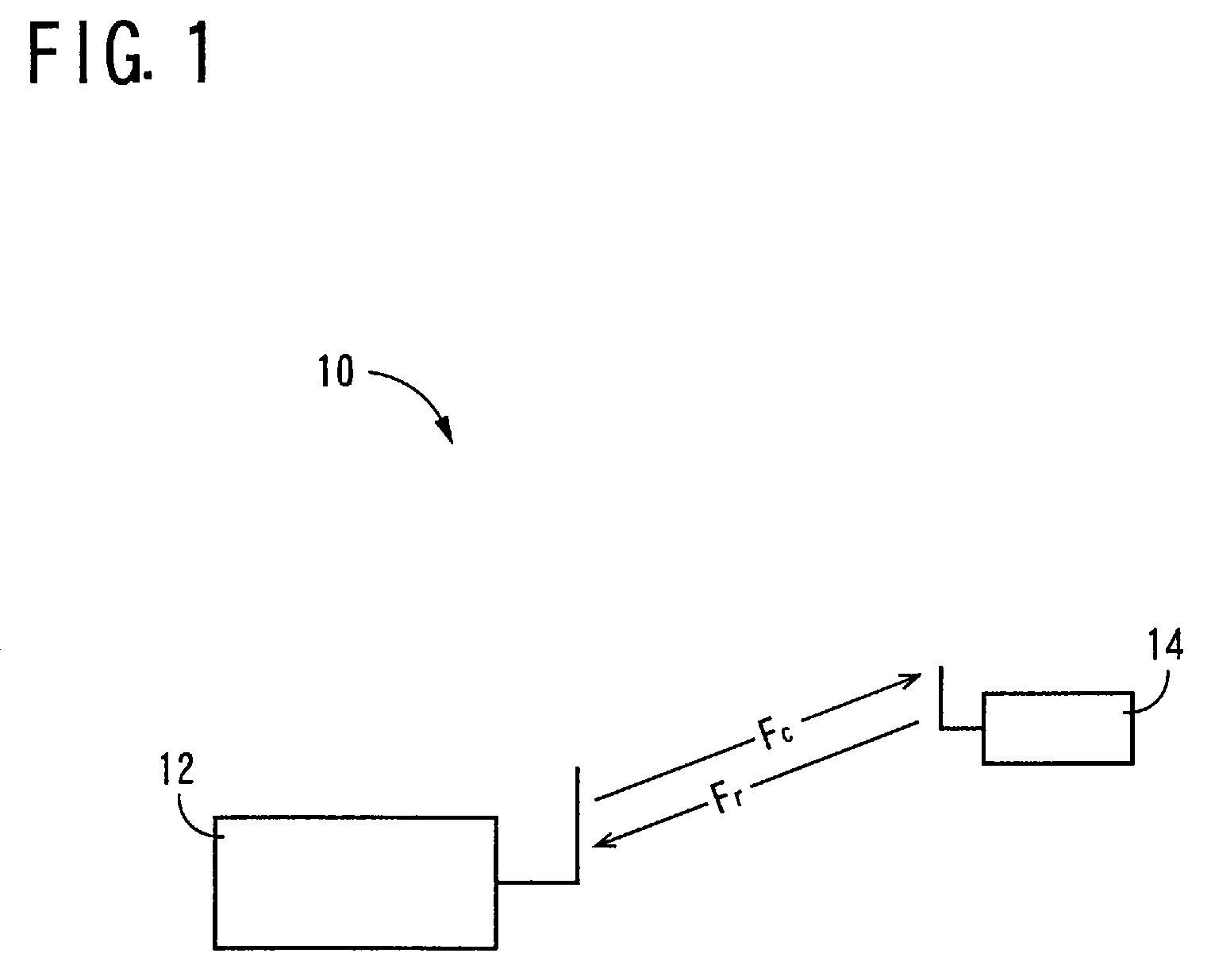
[0046]Referring first to FIG. 1, there is shown a radio-frequency tag communication system 10 to which the present invention is suitably applicable. This radio-frequency tag communication system 10 is a so-called “RFID (Radio-Frequency Identification) system consisting of a radio-frequency tag communication device 12 according to one embodiment of this invention, and at least one radio-frequency tag 14 (one radio-frequency tag 14 shown in FIG. 1) each of which is a communication object for radio communication with the radio-frequency tag communication device 12. The radio-frequency tag communication device 12 functions as an interrogator of the RFID system, while the radio-frequency tag 14 functions as a transponder of the RFID system. Described in detail, the radio-frequency tag communication device 12 is arranged to transmit an interrogating wave Fc(transmitted signal) toward the radio-frequency tag 14, and the radio-frequency tag 14 which has received the interrogating wave Fc mo...

second embodiment

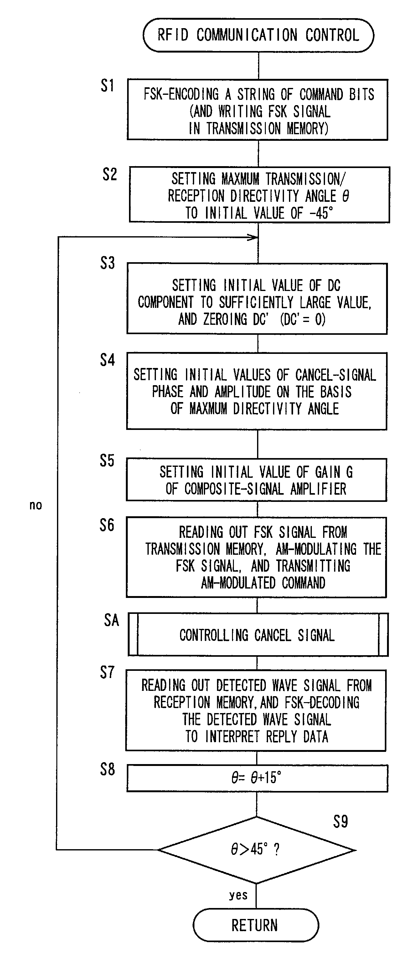
[0074]FIG. 13 is a flow chat illustrating another example of the RFID communication control for radio communication of the radio-frequency tag communication device 12 with the radio frequency tag 14. This RFID communication control is repeatedly executed with a predetermined cycle time. It is noted that the same reference signs as used in FIG. 10 will be used to identify the same steps, which will not be described.

[0075]In the RFID communication control shown in FIG. 13, the above-described step S4 is followed by S10 in which the carrier wave not including any command is transmitted from each of the plurality of transmitter / receiver antenna elements 20, toward the radio-frequency tag 14. Then, the control flow goes to SC in which a provisional control of the cancel signal illustrated in FIG. 14 is implemented. The control flow then goes to the step S5 described above, and further goes to SD in which a final control of the cancel signal illustrated in FIG. 15 is implemented. Then, th...

third embodiment

[0079]FIG. 16 is a view for explaining another example of adjustment of the amplification ratio G of the composite-signal amplifying portion 34. As shown in FIG. 16, the ratio G of amplification of the composite signal by the composite-signal amplifying portion 34 is set each time the phase and / or the amplitude of the cancel signal is / are updated by the cancel-signal control portion 54. Accordingly, the resolution at the first detected-wave-signal A / D converting portion 42 to covert the demodulated signal into the digital signal can be maximized.

[0080]The preferred embodiments of the present invention have been described in detail by reference to the drawings, it is to be understood that the present invention are not limited to the illustrated embodiments, but may be otherwise embodied.

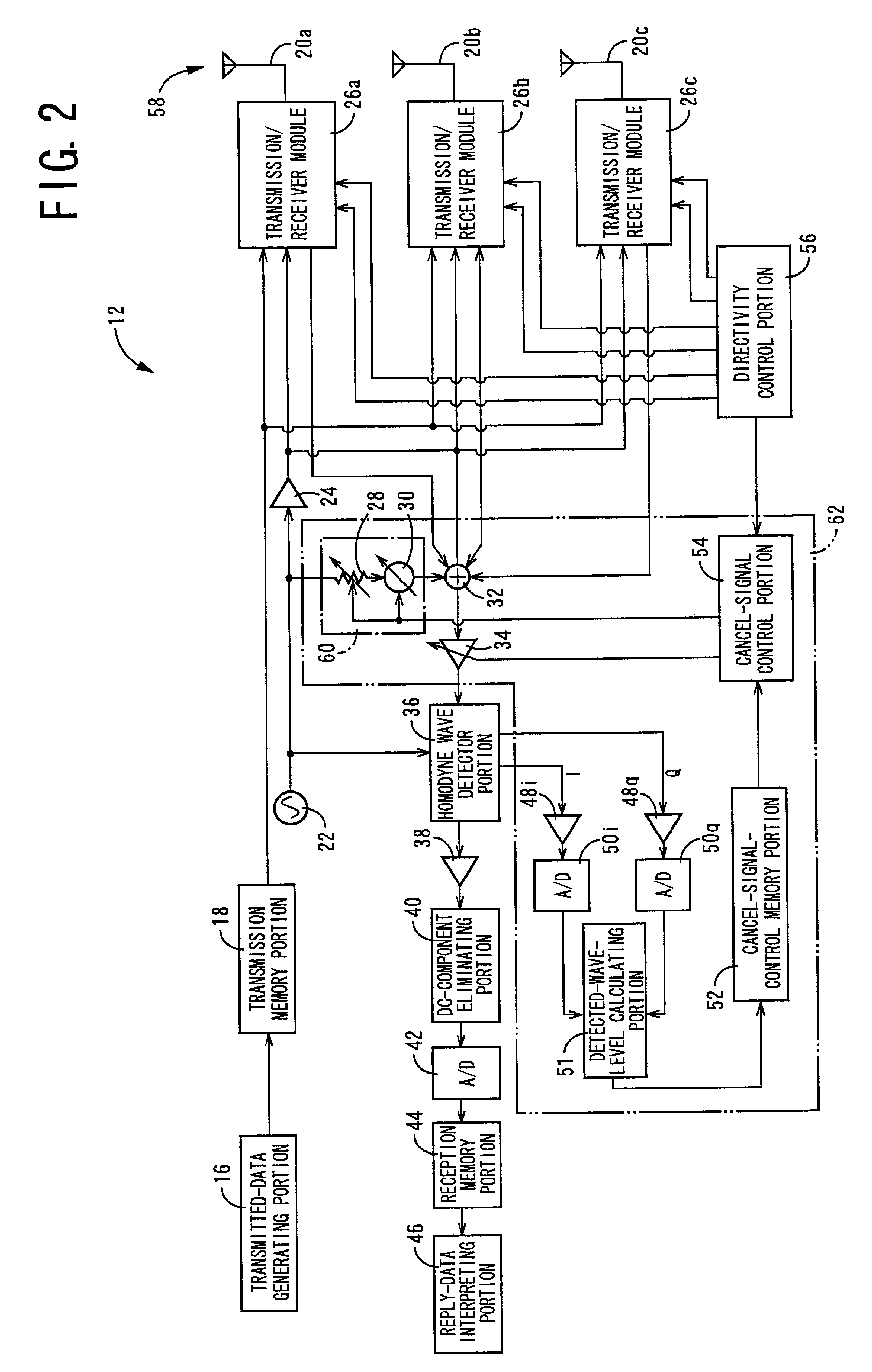
[0081]In the preceding embodiments, the homodyne wave detector portion 36, the cancel-signal control portion 54, the directivity control portion 56, etc. are separate control devices. However, the sep...


PUM


Abstract

A radio-frequency tag communication device including a receiver array antenna device for receiving a reply signal, a cancel-signal generating portion configured to generate a cancel signal for eliminating a leakage signal that is a part of a transmitted signal, which part is received by the receiver array antenna device, a cancel-signal control portion configured to control a phase and / or an amplitude of the cancel signal generated by the cancel-signal generating portion, and a received-signal combining portion configured to combine together received signals received by a plurality of antenna elements of the receiver array antenna device, to obtain a composite signal, and wherein the transmission of the transmitted signal and the reception of the received signals are concurrently controlled, and the cancel signal generated by the cancel-signal generating portion is applied to the received-signal combining portion, whereby the received signals and the cancel signal are combined together, so that a signal / noise ratio of a wave detector output upon demodulation of the composite signal is improved to increase the maximum distance of communication.

Description

[0001]The present application is a Continuation-in-Part of International Application No. PCT / JP2006 / 302188 filed on Feb. 8, 2006, which claims the benefit of Japanese Patent Application No. 2005090499 filed on Mar. 28, 2005.BACKGROUND OF THE INVENTION[0002]1. Field of the Invention[0003]The present invention relates in general to a radio-frequency tag communication device configured to effect radio communication with radio-frequency tags for writing and reading information on and from the radio-frequency tags, and more particularly to techniques for suppressing a received leakage signal which is a part of a transmitted signal.[0004]2. Description of the Related Art[0005]There is known an RFID (Radio-Frequency Identification) communication system wherein a radio-frequency tag communication device (interrogator) reads out information, in a non-contact fashion, from small-sized radio-frequency tags (transponders) on which desired information is written. In this RFID communication syste...

Claims


Application Information

Patent Timeline
Patent Type & Authority Patents(United States)
IPC IPC(8): G08B13/14
CPCH04B5/0062
Inventor KURAMOTO, KATSUYUKI
Owner BROTHER KOGYO KK
Why Eureka
Try Eureka