
Binary continuous phase modulation (CPM) data demodulation receiver

a data demodulation and continuous phase technology, applied in phase-modulated carrier systems, amplitude demodulation, digital transmission, etc., can solve the problem of presenting further detection problems, affecting the decision ability to make correct bit decisions, and severely limited performance of inter-symbol interference (isi), so as to improve data detection, improve data detection, and improve data detection

Active Publication Date: 2012-01-03
THE AEROSPACE CORPORATION
View PDF6 Cites 1 Cited by
  • Summary
  • Abstract
  • Description
  • Claims
  • Application Information

AI Technical Summary

Benefits of technology

The invention is about improving the demodulation of continuous phase modulation (CPM) signals. It aims to enhance the demodulation of low-modulation index CPM signals and provide a demodulator that can convert CPM signals generated using a low modulation index into equivalent high-modulation index CPM signals for improved data detection. The invention is a simple-to-implement non-linear receiver that uses phase unwrapping to reconstruct the original CPM signal and feed it into a conventional demodulator for data detection. The technique reduces the complexity of demodulating small-modulation index CPM signals and optimizes the use of limited communication bandwidths. Overall, the invention simplifies data demodulation and improves data detection.

Problems solved by technology

The disadvantage of the serial demodulator is that its performance may be severely limited by inter-symbol interference (ISI), particularly for small bandwidth-time (BT) products.
The presence of ISI in the signal sample causes the signal to randomly deviate from its expected value and could greatly impair the decision ability to make correct bit decisions, even in the absence of receiver noise.
However, the modulation index h presents further detection problems when the value of h is low.
However, conventional detection of these narrow-band modulation signals is complex and entails a high complexity data demodulator.
Small modulation index partial-response CPM signals are very bandwidth efficient but difficult and complex to demodulate using conventional linear receivers.

Method used


Image

  • Binary continuous phase modulation (CPM) data demodulation receiver
  • Binary continuous phase modulation (CPM) data demodulation receiver
  • Binary continuous phase modulation (CPM) data demodulation receiver

Examples


Embodiment Construction

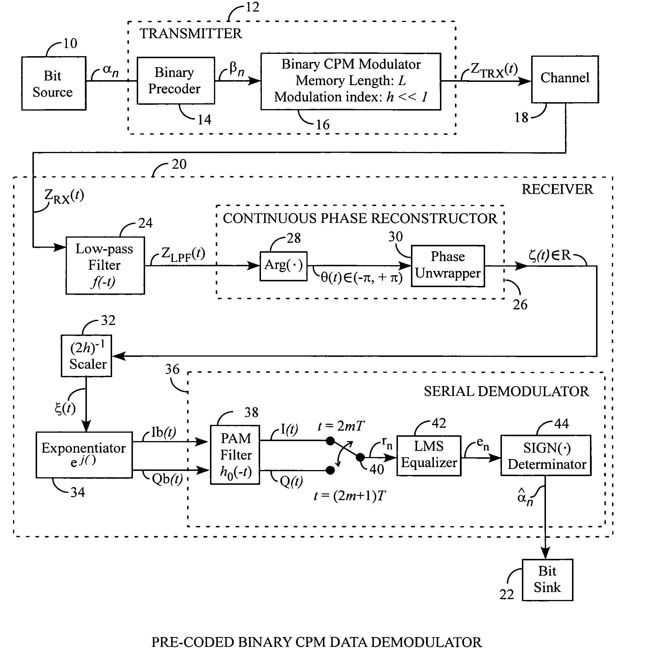
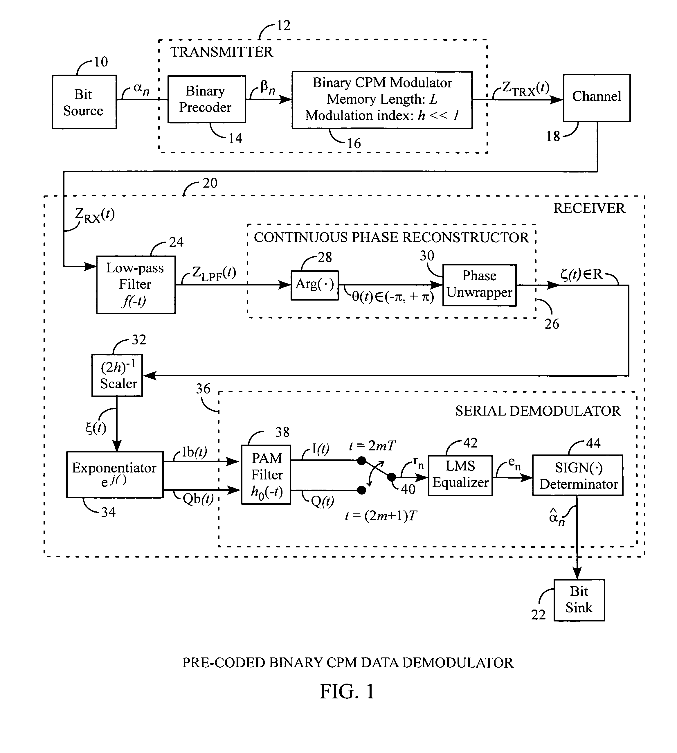
[0017]An embodiment of the invention is described with reference to the FIG. 1 using reference designations as shown in the drawing. A bit source 10 provides a serial bit stream αn to a modulator 12 including a binary precoder 14 for generating a βn serial symbol stream fed to a binary continuous phase modulation (CPM) modulator 16 having a memory length L and a modulation index h. The modulator 16 can be a GMSK modulator using a Gaussian filter, not shown. The modulator 16 provides a ZTX(t) transmitted CPM signal from the transmitter 12. The ZTX(t) transmitted CPM signal is a CPM signal communicated through a channel 18, such as an average white Gaussian noise (AWGN) channel 18.

[0018]The ZTX(t) transmitted CPM signal includes noise as a ZRX(t) received CPM signal received by a demodulation receiver 20 for generating an {circumflex over (α)}n estimated serial bit stream of the original αn serial bit stream from the bit source 10. The {circumflex over (α)}n an estimated serial bit st...


PUM


Abstract

A communications receiver receives a received continuous phase modulation (CPM) signal having an original modulation index of h and includes a filter, a continuous phase reconstructor using phase unwrapping, and a modulation index scaler for generating a reconstructed CPM signal having a scaled modulation index H from the received CPM signal having a small modulation index h, with the scaled modulation index H preferably being greater than the original modulation index h, so that, the transmitted CPM signal occupies a narrow bandwidth, yet, during reception, the reconstructed CPM signal with the high modulation index H can be reliably data demodulated for improved performance with reduced demodulation complexity.

Description

STATEMENT OF GOVERNMENT INTEREST[0001]The invention was made with Government support under contract No. FA8802-04-C-0001 by the Department of the Air Force. The Government has certain rights in the invention.FIELD OF THE INVENTION[0002]The invention relates to the field of continuous phase modulation communication systems. More particularly, the present invention related to a demodulator for demodulating communicated precoded continuous phase modulation signals.BACKGROUND OF THE INVENTION[0003]Continuous phase modulation (CPM) signals are phase-modulated signals having a spectral occupancy that can be tailored to fit limited transmission bandwidths through suitable pre-modulation filtering. Moreover, unlike non-constant envelope signals, such as amplitude-modulated signals or filtered phase-modulated signals, the CPM signals have a constant envelope and allow saturated power amplifier operation for maximum power efficiency. These desirable signal properties, desirable by the rising ...

Claims


Application Information

Patent Timeline
Patent Type & Authority Patents(United States)
IPC IPC(8): H04L27/22
CPCH04L27/2003H04L27/2334
Inventor LUI, GEE L.TSAI, KUANG
Owner THE AEROSPACE CORPORATION
Learn More