

Deployment handle for an implant deployment device
a deployment device and deployment handle technology, applied in the field of deployment handle for implant deployment device, can solve the problems of large force required to withdraw such a sheath, inability to exert much control over the withdrawal process, and difficult method, etc., and achieve the effect of improving the deployment handle and improving the deployment assembly
- Summary
- Abstract
- Description
- Claims
- Application Information
AI Technical Summary
Benefits of technology
Problems solved by technology
Method used
Image

Examples
Embodiment Construction
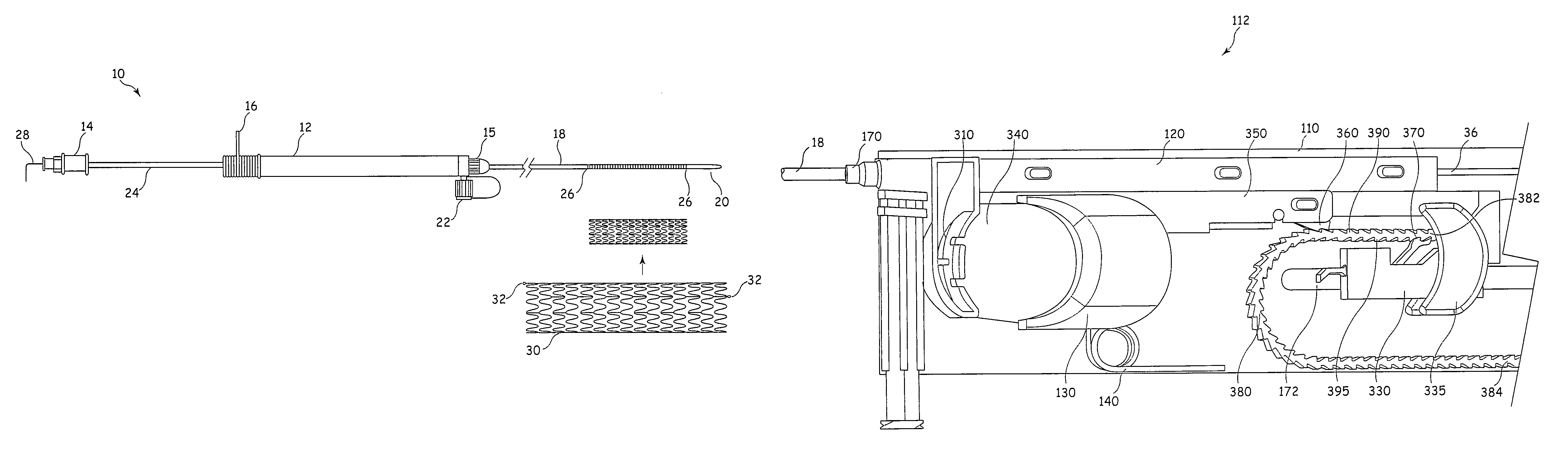
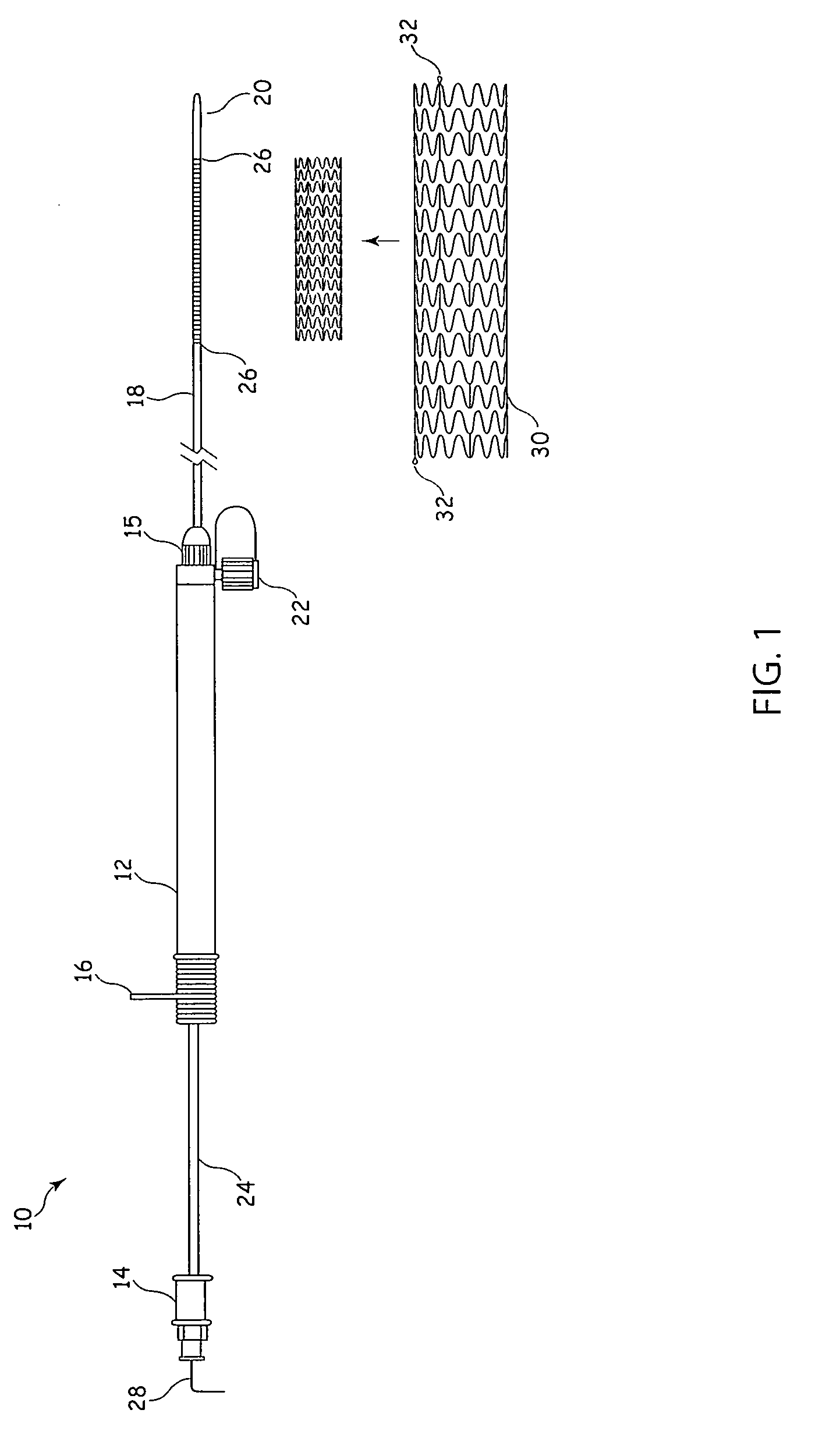
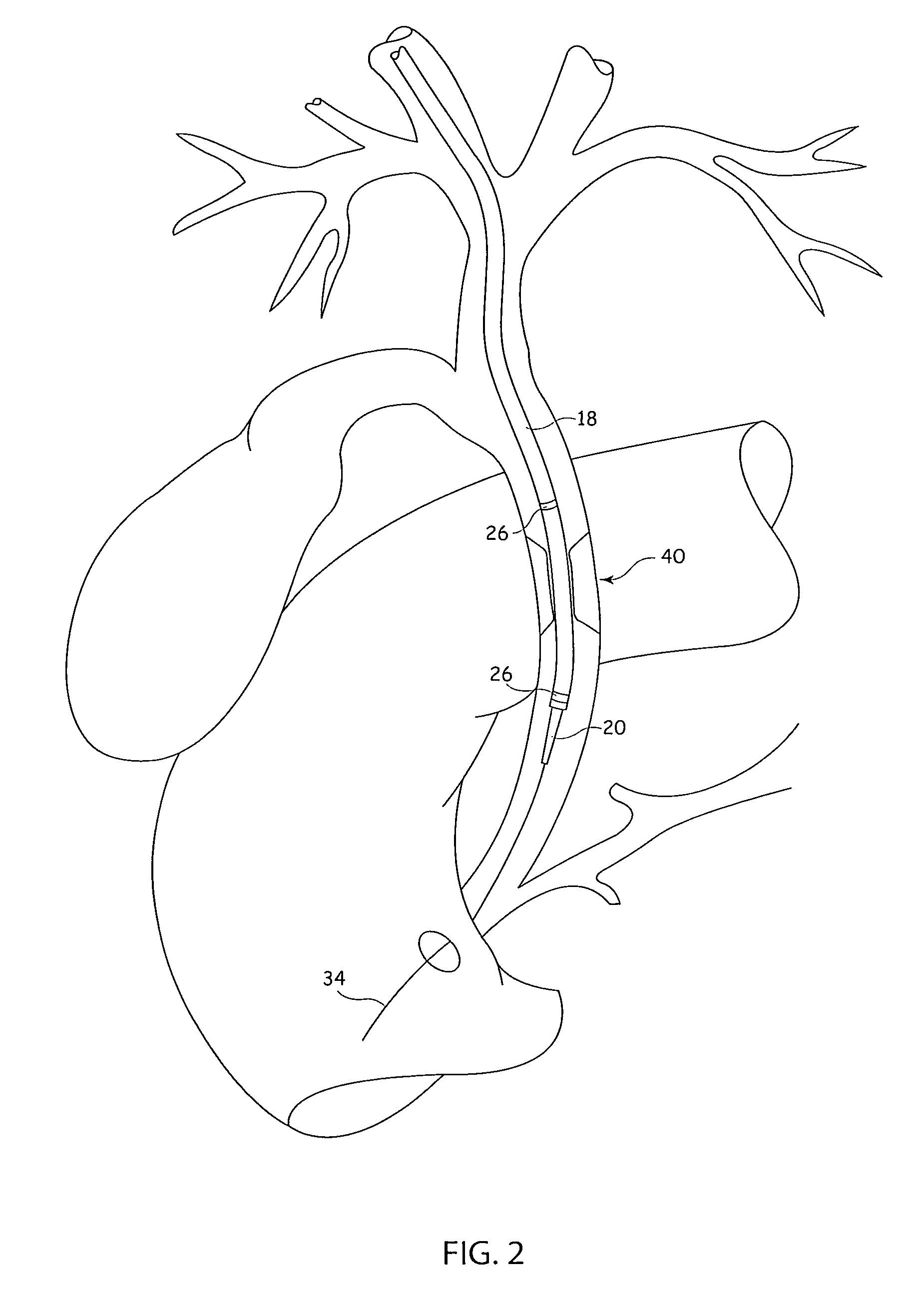
[0032]It is to be understood that the Figures are schematic and do not show the various components in their actual scale. In many instances, the Figures show scaled up components to assist the reader.
[0033]In this description, when referring to a deployment assembly, the term distal is used to refer to an end of a component which in use is furthest from the surgeon during the medical procedure, including within a patient. The term proximal is used to refer to an end of a component closest to the surgeon and in practice in or adjacent an external manipulation part of the deployment or treatment apparatus.
[0034]On the other hand, when referring to an implant such as a stent or stent graft, the term proximal refers to a location that in use is closest to the patient's heart, in the case of a vascular implant, and the term distal refers to a location furthest from the patient's heart.
[0035]The example of delivery system shown in FIGS. 1 to 3 is the applicant's delivery system for its Zi...
PUM
 Abstract
Description
Claims
Application Information