Transmission control apparatus

a technology of transmission control and control apparatus, which is applied in the direction of fluid gearings, gearings, instruments, etc., can solve the problems of affecting the operation of the transmission control apparatus, the failure of the electric motor, and the possibility of failure, such as line disconnection or short circuit, to prevent the deterioration of fuel consumption or drivability oriented failures

Active Publication Date: 2012-01-10
MITSUBISHI ELECTRIC CORP
View PDF7 Cites 0 Cited by
  • Summary
  • Abstract
  • Description
  • Claims
  • Application Information

AI Technical Summary

Benefits of technology

[0013]Accordingly, the present invention has been made to overcome the foregoing problems, and it is an object of the invention to provide a transmission control apparatus which can detect a drop in power transmission performance of a clutch actuator, and prevent a failure thereof.
[0015]The transmission control apparatus according to the invention predicts or detects clutch slipping which is caused by a reduction in power transmission performance, thus making it possible to prevent the clutch actuator from failing and prevent the failure-oriented deterioration of fuel consumption or deterioration of drivability.

Problems solved by technology

When the power transmission performance of the clutch becomes lower, clutch slipping occurs, causing friction to generate heat at the clutch portion.
When the internal temperature of the coil becomes a failure limit temperature or higher, the high temperature causes a chemical reaction of the coat of the insulator, which damages the insulation of the conductive wire or disconnects the soldered portion of the coil, resulting in a failure of the electric motor.
As described above, when the performance-dropped state of the electric motor continues and the motor temperature rises, a failure, such as line disconnection or short-circuiting, is likely to occur.
When a failure in one of electric motors used in the twin-clutch transmission cannot be prevented and one electric motor fails, this electric motor cannot generate a torque, so that the clutch which is operated by the electric motor cannot transmit power from the input shaft to the output shaft.
Accordingly, gear shifting of the transmission is carried out only with the clutch that includes the other electric motor, so that the gear ratio of the transmission cannot be set to one which ensures a high fuel consumption effect.
Because the adequate gear ratio cannot be selected, the acceleration intended by a driver may not be actuated or the high-speed driving may make the engine sound louder, which is the deterioration of the drivability.
Further, the gear shifting operation at a gear ratio far different from the normal one would bring about a problem of a continuous state where, for example, the gear shifting shock would become greater.
The transmission control apparatus disclosed in the Patent Document 1 has problems such that although the transmission control apparatus can detect a failure after the clutch actuator has failed, it cannot detect that the clutch actuator is in a performance-dropped state while the driving of the clutch actuator is being instructed, and thus keeps operating until the clutch actuator fails, so that the failure cannot be prevented.

Method used


Image

  • Transmission control apparatus
  • Transmission control apparatus
  • Transmission control apparatus

Examples


first embodiment

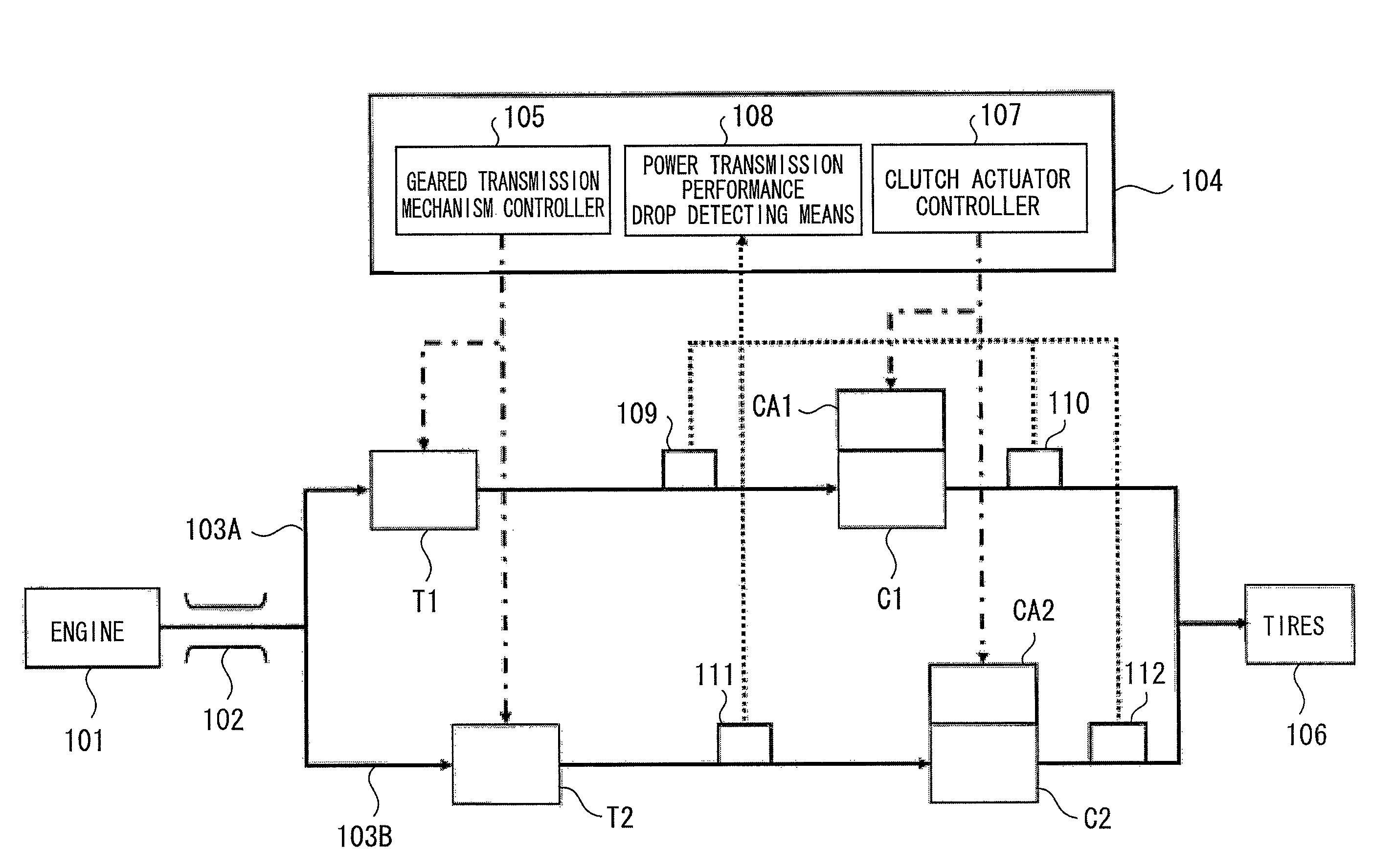
[0027]FIG. 1 is a system configurational diagram illustrating a transmission control apparatus according to a first embodiment of the invention. In FIG. 1, an engine 101 outputs power and transmits the power to an engine output shaft 102. The power transmitted to the engine output shaft 102 is transmitted to a first geared transmission mechanism T1 through a first power transmission path 103A. The first geared transmission mechanism T1 can perform a gear shifting operation as the power is transmitted by the gear that is specified by a geared transmission mechanism controller 105 which constitutes a transmission control apparatus 104.

[0028]Likewise, the power transmitted to the engine output shaft 102 is transmitted to a second geared transmission mechanism T2 through a second power transmission path 103B. The geared transmission mechanism controller 105 also gives an instruction to the second geared transmission mechanism T2 to enable a gear shifting operation.

[0029]The powers outpu...

second embodiment

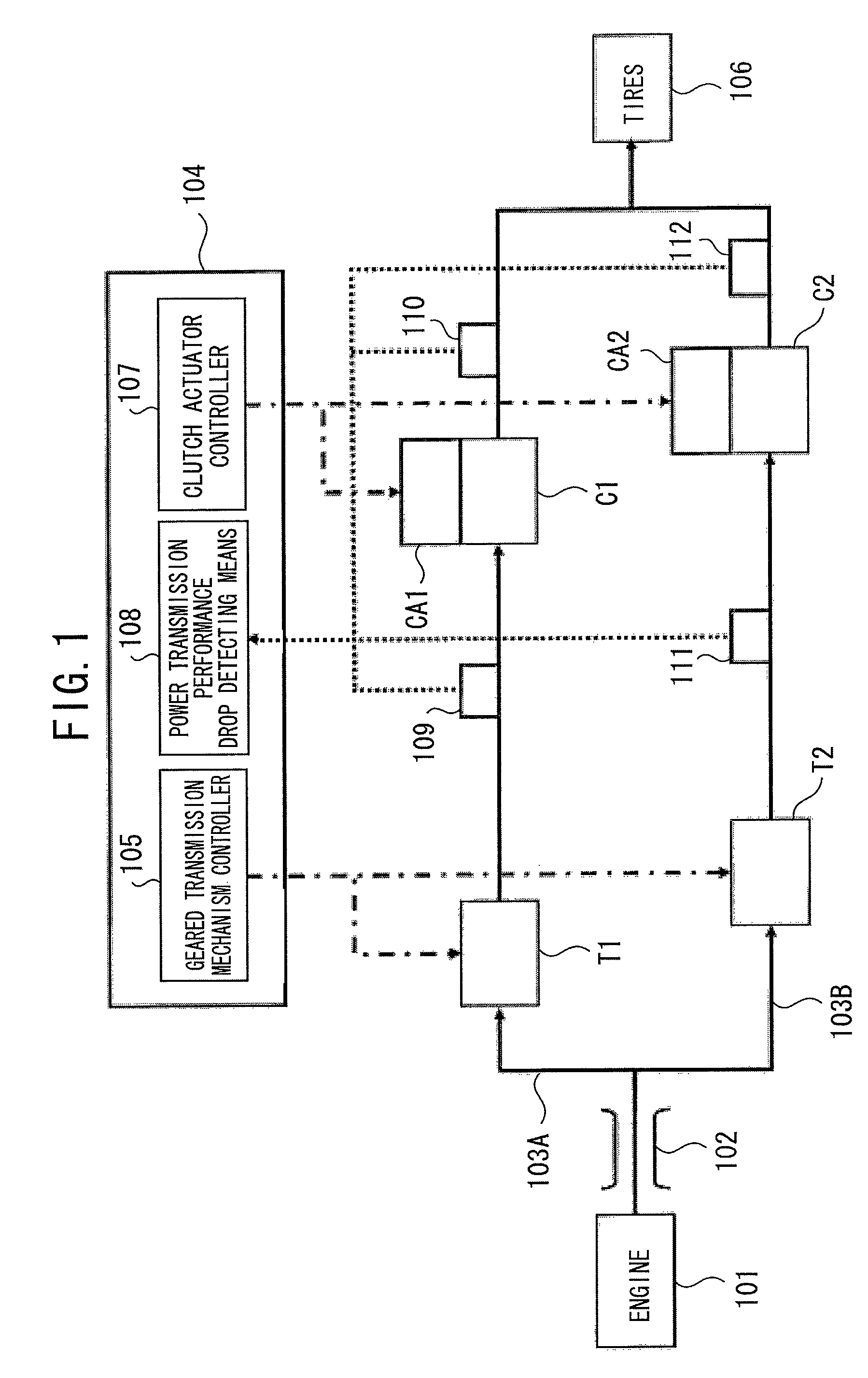
[0040]Next, a transmission control apparatus according to a second embodiment of the invention will be described referring to FIG. 3. Because the system configuration is similar to that of the transmission control apparatus explained in the foregoing description of the first embodiment, FIG. 1 will be used.

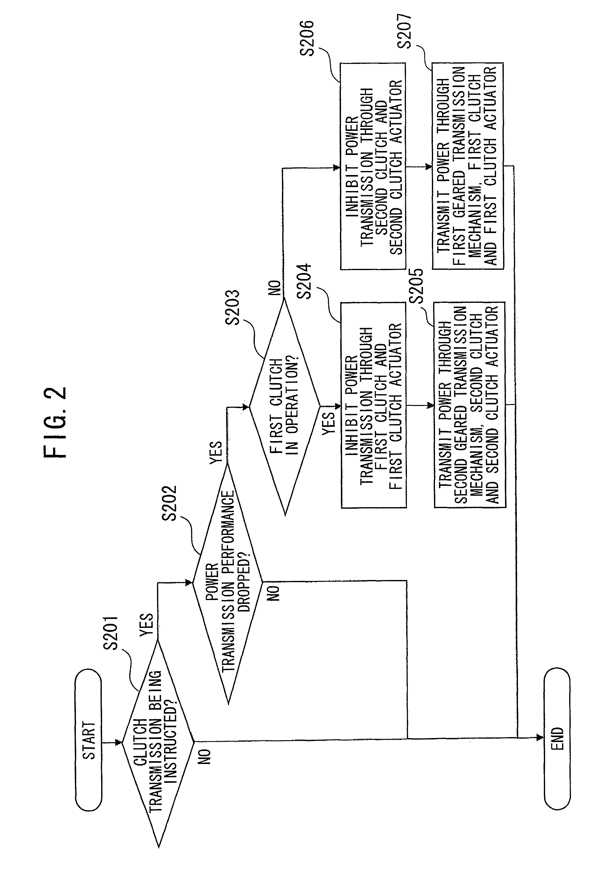
[0041]FIG. 3 is a flowchart illustrating the operation of the transmission control apparatus according to the second embodiment. Referring to FIG. 3, in step S301, it is determined whether the clutch actuator controller 107 is instructing the first clutch actuator CA1 and / or the second clutch actuator CA2 to transmit the torque in the first clutch C1 and / or the second clutch C2. When the determination is YES, the flow proceeds to step S302. Otherwise, the subroutine is terminated.

[0042]In step S302, it is determined whether the first clutch C1 is in operation. When the first clutch C1 is in operation, the flow proceeds to step S303. Otherwise, the flow proceeds to step S306.

[0043]...

third embodiment

[0050]Next, a transmission control apparatus according to a third embodiment of the invention will be described referring to FIGS. 4 and 5. FIG. 4 is a system configurational diagram illustrating the transmission control apparatus according to the third embodiment. In FIG. 4, an engine 401 outputs power and transmits the power to an engine output shaft 402. The power transmitted from the engine 401 is transmitted to tires 403 through the engine output shaft 402.

[0051]The power output from the engine output shaft 402 is transmitted to the first geared transmission mechanism T1 through gears 404a, 404b and 404c provided in the power transmission path of the engine output shaft 402. The first geared transmission mechanism T1 can perform a gear shifting operation by transmitting the power via a specified gear.

[0052]Likewise, the power output from the engine output shaft 402 is transmitted to the second geared transmission mechanism T2 through gears 405a, 405b and 405c provided in the po...


PUM


Abstract

A transmission control apparatus detects a drop in power transmission performance of a clutch actuator, and prevents a failure thereof. When power transmission performance drop detecting means detects a drop in power transmission performance of a first clutch even if a power transmission instruction is given to a first clutch actuator, power transmission in a power transmission path through a first geared transmission mechanism is inhibited, and power transmission in a power transmission path through a second geared transmission mechanism is carried out. When the power transmission performance drop detecting means detects a drop in power transmission performance of a second clutch even if the power transmission instruction is given to a second clutch actuator, power transmission in the power transmission path through the second geared transmission mechanism is inhibited, and power transmission in the power transmission path through the first geared transmission mechanism is carried out.

Description

BACKGROUND OF THE INVENTION[0001]1. Field of the Invention[0002]The present invention relates to a transmission control apparatus that controls the transmission mounted in a vehicle, such as an automobile, and, more particularly, to a transmission control apparatus that controls the transmission which separates power from an engine to two power transmission paths each having an independent clutch and an independent transmission mechanism.[0003]2. Description of the Related Art[0004]There has been a so-called twin-clutch transmission which separates power from an engine to two power transmission paths each having an independent clutch and an independent transmission mechanism, and performs a transmission operation to transmit power from the input shaft to the output shaft. This twin-clutch transmission uses an electric motor as an actuator to actuate the clutch (see, for example, Non-patent Document 1 (“Electromotoric actuators for double clutch transmissions” which is the document d...

Claims


Application Information

Patent Timeline
Patent Type & Authority Patents(United States)
IPC IPC(8): B60W10/02G06F17/00F16D48/06F16H59/46F16H59/50F16H61/02F16H61/12F16H61/68F16H61/684F16H61/688
CPCF16D48/064F16H61/12F16D2500/3022F16D2500/30406F16D2500/30421F16D2500/5108Y10T74/19149F16D2500/7105F16H61/688F16H2061/1224F16H2061/1276F16D2500/5114
Inventor KAMIOKA, NOZOMUYONEZAWA, SHIROOKABE, TAKERUSHODA, TOMOHISAHORII, MASAKIOGAWA, YASUFUMIISHIKAWA, OSAMU
Owner MITSUBISHI ELECTRIC CORP
Why Eureka
Try Eureka