Fixed type constant velocity joint

a constant velocity joint, fixed technology, applied in the direction of yielding couplings, rotary machine parts, couplings, etc., can solve the problems of reducing the strength and durability of cages, limiting the assembly angle of joints, and single circular groove shape of rzeppa joints, etc., to achieve suitable strength and durability, reliable construction

Active Publication Date: 2012-01-17
WIA CORP
View PDF10 Cites 17 Cited by
  • Summary
  • Abstract
  • Description
  • Claims
  • Application Information

AI Technical Summary

Benefits of technology

[0010]Accordingly, in view of the drawbacks and disadvantages associated with the conventional joints, the present invention is directed to a fixed type constant velocity joint with reliable construction and suitable strength and durability.
[0011]The present invention is also directed to a fixed type constant velocity joint with compact structure, and having suitable strength, durability, and load capacity. The present invention is also directed to provide an improved structure and construction for the fixed type constant velocity joints, which can effectively be applicable to the six-ball type joint, which is presently popular for conventional vehicles, and also to the more energy-efficient joints of eight-ball and ten-ball types, etc., which contain many torque-transmitting balls. The present invention is also directed to provide a novel and improved structure to the fixed type constant velocity joint, which can further provide a suitable and sufficient strength and durability to the ball cage (particularly to the web portions of the cage) which is typically susceptible to damage due to the repeated application of high stresses, in particular, onto the cage windows through plural (i.e., six or more) balls received therein to transmit rotational torque between the joint shafts.
[0012]As briefly disclosed above, the structures of the conventional Rzeppa joint and undercut-free joint each have both advantages and disadvantages in view of cage strength or durability. For increasing the cage strength and durability, there are typically two main methods. One method is to reduce the contact force by the reduction of funnel angle, and the other is to increase the cage web area by the reduction of joint assembly angle and maximum ball movement in the cage. In order to accomplish these objectives, the present invention provides the ball groove shape to have a variable funnel angle by providing a composite groove configuration (to be described below in detail) which leads to a reduction in the total funnel angle and the joint assembly angle.
[0014]The present invention provides a reduction of joint assembly angle as compared to the Rzeppa joint and a reduction of funnel angle as compared to the undercut-free joint, simultaneously, by the ball groove shape which is composed essentially of two circles with different center offsets and a tangential line segment between these two circles (as will be described in detail below). An advantage in having the ball groove shape of the invention is that it can provide some flexibility in determining the funnel angle and the joint assembly angle by suitably adjusting the position of two center offsets in the ball grooves.

Problems solved by technology

In particular, the funnel angle of the undercut-free joint at the straight groove range is increased seriously as the retaining ball approaches to the outer edge of the track grooves, and it causes to increase the contact force F, and thus, results in the reduction in cage strength and durability.
However, as compared with the straight groove of undercut Joint, the single circular groove shape of the Rzeppa joint has also a disadvantage of limiting the assembly angle of the joint, as described above.

Method used


Image

  • Fixed type constant velocity joint
  • Fixed type constant velocity joint
  • Fixed type constant velocity joint

Examples


embodiment 1

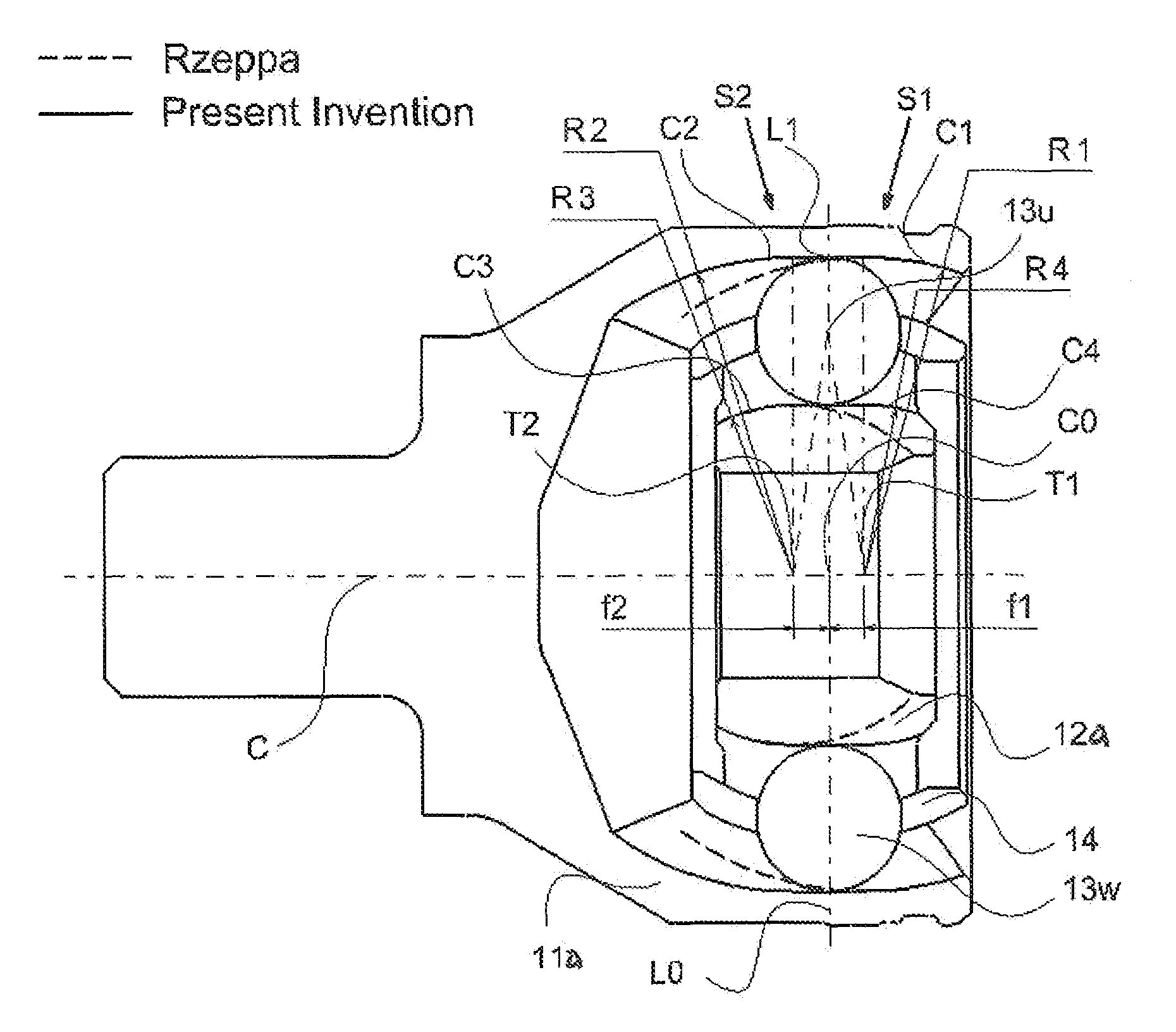
[0037]With reference to FIGS. 5(a)-5(c), the first embodiment of the invention is described herein. As illustrated in FIG. 5(a), a fixed type constant velocity joint of this embodiment includes a plurality of (namely, six, eight, or more) ball guiding tracks each defined by a pair of corresponding inner and outer ball grooves. The ball grooves define variable funnel angles therein, and the cross sectional shape of each groove is composed essentially of two circular regions with different centers (thus, in offsets) and an intermediate linear segment connecting tangentially between the two circles. As mention above, the funnel angle is defined as the angles between the tangential lines at the ball contact points in the outer ball grooves and inner ball grooves when the joint is in a specific joint operating angle.

[0038]As shown in FIG. 5(a), the ball groove of outer race 11a includes circular region C1 (i.e., a first circular region) disposed at a first lateral side S1 (or right side ...

embodiment 2

[0041]With reference to FIGS. 6(a)-6(d), the second embodiment of the invention is described herein, directed to another application of the variable funnel angle groove structure of the invention, one example of which described above in connection with the first embodiment. This embodiment includes common aspects with the first embodiment, however, having certain differences as described below.

[0042]While the groove shape shown in the first embodiment (i.e., FIG. 5) has the horizontally-formed groove region for linear portion (L1), the present embodiment as illustrated in FIG. 6(a) provides an inclined linear groove region. In this structure, the ball groove of outer race 11b includes circular region C1 (i.e., a first or right side circular region) with radius R1 and center T1′, circular region C2 (i.e., a second or left side circular region) with radius R2 and center T2′, and the linear region L1 connecting and extending tangentially between the two circular regions C1 and C2. Like...

embodiment 3

[0044]With reference to FIGS. 7(a)-7(d), the third embodiment of the invention is described herein, directed to another application of the variable funnel angle groove structure of the invention, examples of which described above in connection with the first and second embodiments. The present embodiment includes common aspects with the second embodiment, however, having certain differences as described below.

[0045]Similar to the groove shape of the second embodiment (i.e., FIG. 6), the present embodiment as illustrated in FIG. 7(a) provides an inclined or sloped linear groove region L1. However, in this embodiment, center T2″ of circular groove C2 of outer race 11c and center T4″ of circular groove C4 of inner race 12c are located in the opposite side of the joint center line L0. As illustrated in FIGS. 7(b) and 7(c), this application does not provide a substantial advantage for the improvement of strength and durability of outer race 11 and inner race 12, as well as, for the reduc...


PUM


Abstract

A constant velocity joint for a drive system comprises: an outer race having a plurality of guide grooves formed in an axial direction in the inner spherical surface of the outer race; an inner race having a plurality of guide grooves formed in an axial direction in the outer spherical surface of the inner race, said guide grooves of the outer race and the inner race together forming a plurality of ball guide tracks; a plurality of balls disposed in the ball guide tracks; and a cage installed between the inner spherical surface of the outer race and the outer spherical surface of the inner race, said cage having a plurality of windows for retaining the balls therein. Each guide groove of the outer race is shaped to have a longitudinal cross section formed with two circular regions with different centers, a first circular region disposed at a first lateral side of the outer race and a second circular region disposed at a second lateral side of the outer race, and a linear region tangentially extending between these two circular regions, and each guide groove of the inner race is shaped to have a longitudinal cross section formed with two circular regions with different centers, a first circular region disposed at a first lateral side of the inner race and a second circular region disposed at a second lateral side of the inner race, and a linear region tangentially extending between these two circular regions.

Description

FIELD OF THE INVENTION[0001]The present invention relates to a constant velocity joint, and more particularly, to a fixed type constant velocity joint for a drive system, which is typically used in a drive axle of, for example, an automobile for transmitting rotational torque between the rotating shafts with relatively high operating angle.BACKGROUND OF THE INVENTION[0002]Constant velocity joints typically used in the drive system of vehicles for transferring a rotational torque, are classified typically into the fixed type joint allowing only angular displacement between the axles and the plunging type joint allowing both angular and axial displacement between the axles. The fixed type constant velocity joint is required to operate with a relatively high operating of, for example, 450 or more, as compared to the plunging type joint.[0003]FIG. 1 illustrates a conventional fixed type constant velocity joint known as a Rzeppa type constant velocity joint (referred hereinafter as a “Rz...

Claims


Application Information

Patent Timeline
Patent Type & Authority Patents(United States)
IPC IPC(8): F16D3/223
CPCF16D3/223F16D3/2245F16D2003/22303Y10S464/906
Inventor OH, SEUNG TARKKIM, TAE HONG
Owner WIA CORP
Why Eureka
Try Eureka