Vehicular electric power source controller

a technology of electric power source controller and electric motor, which is applied in the direction of electric devices, machines/engines, safety/protection circuits, etc., can solve the problems of increasing wasteful standby current (dark current) and wasteful consumption of limited electric power source, and achieve the effect of reducing wasteful electricity consumption

Active Publication Date: 2012-01-17
TOYOTA JIDOSHA KK +1
View PDF21 Cites 13 Cited by
  • Summary
  • Abstract
  • Description
  • Claims
  • Application Information

AI Technical Summary

Benefits of technology

[0009]The invention provides a vehicular electric power source controller that reduces wasteful electricity consumption when the vehicle is parked while operating an electrical load that is used while the vehicle is parked.
[0011]Therefore, the performance of the switching operation by the first switching device electrifies not only the first electrical load but also the second electrical load. When the vehicle is parked, the performance of the switching operation by the second switching device electrifies only the second electrical load. Hence, if an electrical load that is used while the vehicle is parked is assigned as a second electrical load, wasteful electricity consumption is reduced while the vehicle is parked.
[0012]When the first switching device outputs an on-command to electrify the second electrical load, the second switching device outputs an off-command to deelectrify the second electrical load. Therefore, even when the second switching device outputs the on-command to electrify the second electrical load, the second switching device outputs the off-command to deelectrify the second electrical load if the first switching device outputs the on-command to electrify the second electrical load. Hence, it is possible to prevent the continuation of a state in which the on-command is output from both the first and second switching devices, and to avoid the interference by the on-commands from the first and second switching devices.
[0018]The second electrical load may further include an electrical load that is needed in order to control air-conditioning in a cabin. When the vehicle is parked, the electrification of only the air-conditioning-related electrical load may be accomplished by performing the switching operation via the second switching device. Therefore, the condition in the cabin can be made comfortable while the vehicle is parked, and the wasteful electricity consumption is reduced.
[0020]According to the aspect of the invention, even though a desired electrical load is used while the vehicle is parked, the wasteful electricity consumption is reduced.

Problems solved by technology

Thus, there will be wasteful consumption of the limited amount of electric power of the source, such as the battery or the like.
If a construction in which an electrical load that is desired to be used while the vehicle is parked can be operated even when the accessory electric power source and the ignition electric power source are in the non-electrified state (e.g., a construction in which an electrical load that is desired to be while it vehicle is parked is constantly connected to the battery) is adopted, the wasteful stand-by current (dark current) will increase.

Method used


Image

  • Vehicular electric power source controller
  • Vehicular electric power source controller
  • Vehicular electric power source controller

Examples


first embodiment

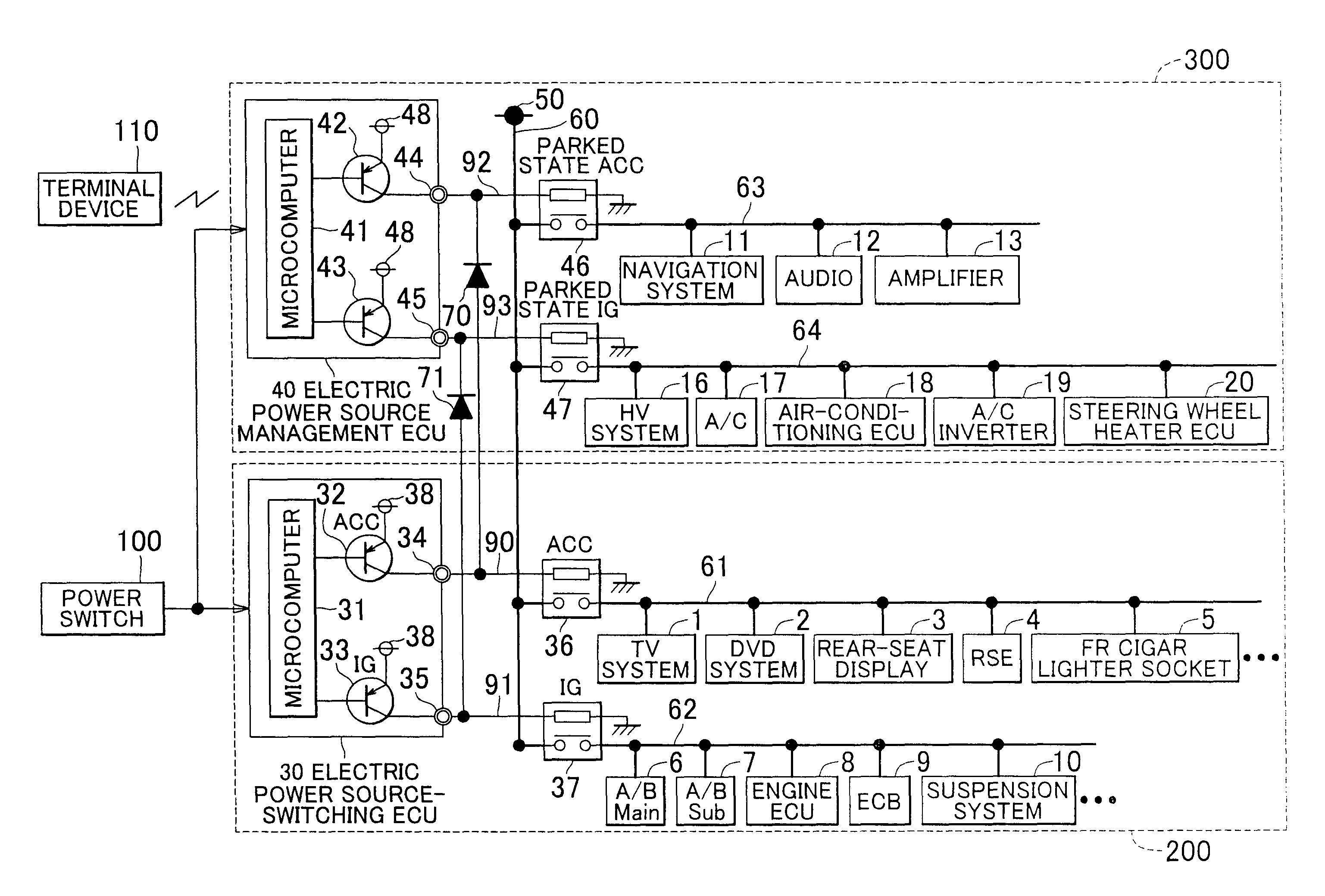
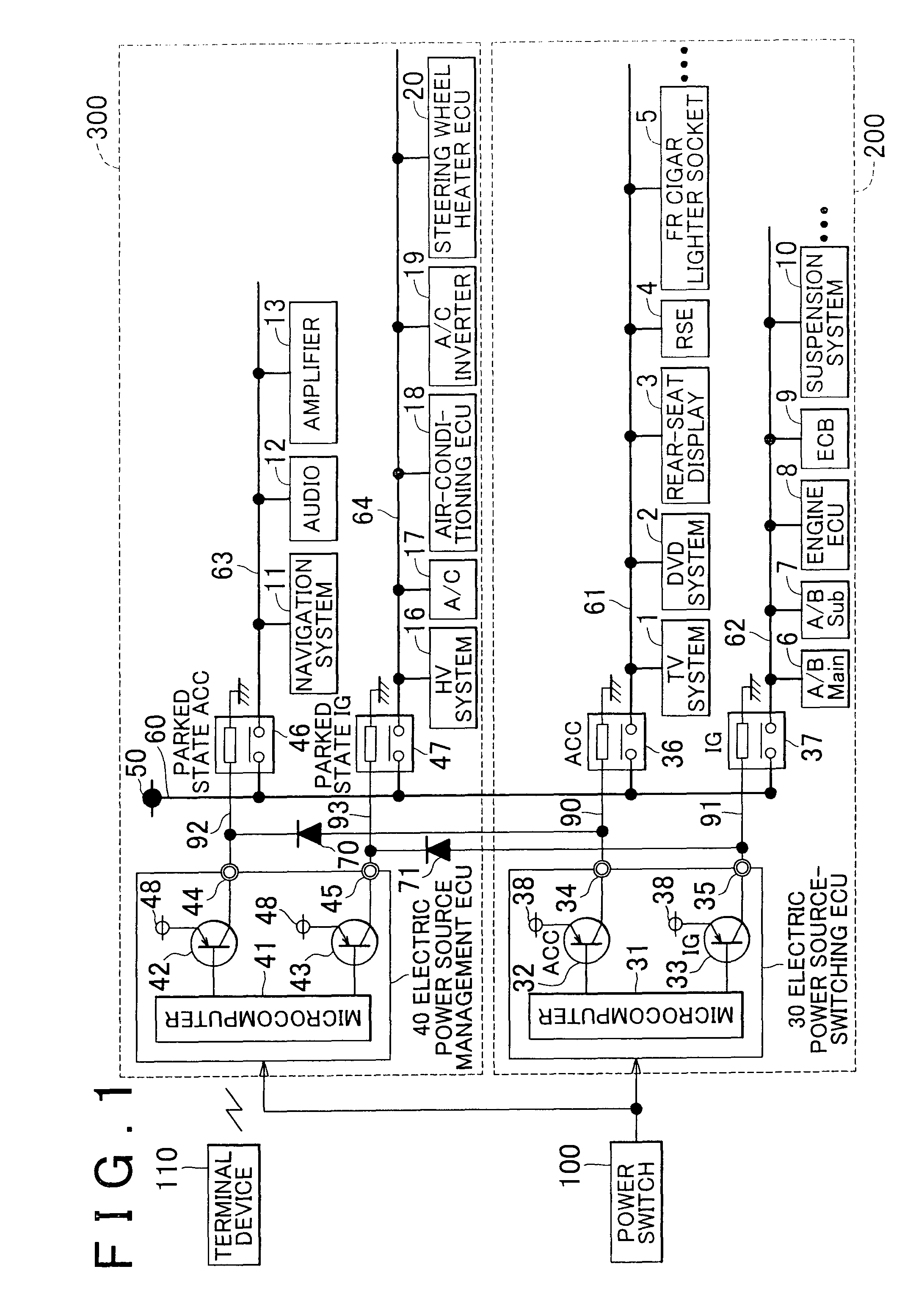
[0030]FIG. 1 is a schematic diagram showing the vehicular electric power source controller in accordance with the invention. A plurality of electrical loads are mounted in a vehicle. The electrical loads are partially shown in FIG. 1. An electric power source 50 supplies electric power to each electrical load. An electricity storage device, such as a predetermined voltage type (e.g., 14 V type) battery or the like, is connected to the electric power source 50. Furthermore, an electric power generator, which generates electricity by converting kinetic energy to electric energy, may be connected to the electric power source 50. The electric power generator generates electric power using the output of the engine that is provided for running the vehicle. The electric power generated by the electric power generator is supplied to each electrical load, as in the case of an electricity storage device such as a battery or the like. A concrete example of the electric power generator is an al...

second embodiment

[0067]In the second embodiment, the vehicular electric power source controller is applied to a remote engine start system. The remote engine start system (hereinafter, simply referred to as “remote start” or “remote starter”) is a system that starts the engine of the vehicle by a remote control from outside the vehicle. The remote starter is often used to clear the frost or snow impeding visibility or perform the air-cooling or heating before the user enters the vehicle. The electrical loads that need to be operated to accomplish such purposes are loads that consume relatively large electric power, for example, a rear defogger, a de-icer, a mirror heater, an air-conditioner compressor, etc. Because the engine, when started by the remote starter, is operated in an idling state, the rotation speed of the engine is low and the amount of electric power generated by the generator (alternator) is small. Therefore, it is often the case that electric power supplied from the battery. Hence, ...


PUM


Abstract

A vehicular electric power source controller that controls the electrification of an electrical load mounted in a vehicle includes: a first electrical load that are a portion of the electrical load mounted in the vehicle; a second electrical load that are electrified preferentially over first electrical loads when a vehicle is parked; an electric power source-switching ECU, an ACC relay and an IG relay that switch not only the electrification of the first electrical load to but also the electrification of the second electrical load; and an electric power source management ECU, a parked state ACC relay and a parked state IG relay that switch the electrification of only the second electrical load. The vehicular electric power source controller curbs wasteful electricity consumption while operating an electrical load that is used while the vehicle is parked.

Description

BACKGROUND OF THE INVENTION[0001]1. Field of the Invention[0002]The invention relates to a vehicular electric power source controller that controls the electrification of an electrical load mounted in a vehicle.[0003]2. Description of the Related Art[0004]A conventional air-conditioner control device detects the state of an electric power source, such as the voltage of a high-voltage battery or the like, via a battery management controller. The air-conditioner control device sends an activation signal to an air-conditioner controller in accordance with the result of the detection to activate an electrically powered compressor, and operates the electrically powered compressor to condition the air in the cabin via the air-conditioner controller that is supplied with the activation signal (e.g., see Japanese Patent Application Publication No. JP-A-8-20232). The control device of the air-conditioning device detects the state of an electric power source, such as the voltage of the high-v...

Claims


Application Information

Patent Timeline
Patent Type & Authority Patents(United States)
IPC IPC(8): B60L1/00
CPCH02J7/0032B60R16/03H02J2310/46
Inventor ESAKA, TOSHINORIFUKASAWA, MINORUTSUTSUMI, HIROSHI
Owner TOYOTA JIDOSHA KK
Why Eureka
Try Eureka