Supercharge Your Innovation With Domain-Expert AI Agents!

Energy-absorbing device, in particular in the form of a safety device against shock loads for a track-borne vehicle

a technology of energy-absorbing devices and track-borne vehicles, which is applied in the direction of shock absorbers, elastic dampers, bumpers, etc., to achieve the effects of high shock, simplified construction of energy-absorbing devices, and easy to mov

Active Publication Date: 2012-01-24
VOITH PATENT GMBH
View PDF10 Cites 6 Cited by
  • Summary
  • Abstract
  • Description
  • Claims
  • Application Information

AI Technical Summary

Benefits of technology

The solution effectively dissipates high shock energies with reduced weight and complexity, providing a lightweight and efficient energy absorption mechanism suitable for high-impact scenarios while ensuring structural integrity and containment of fragments.

Problems solved by technology

Energy-absorbing devices designed to be destroyed which are known from the prior art are in particular deformation tubes or crash boxes in which shock energy is destructively converted into work done in deformation and heat by a defined plastic deformation.

Method used


Image

  • Energy-absorbing device, in particular in the form of a safety device against shock loads for a track-borne vehicle
  • Energy-absorbing device, in particular in the form of a safety device against shock loads for a track-borne vehicle
  • Energy-absorbing device, in particular in the form of a safety device against shock loads for a track-borne vehicle

Examples


Embodiment Construction

[0033]In what follows, a first exemplary embodiment of the energy-absorbing device 100 according to the present invention will be described by reference to the views shown in FIGS. 1 to 3.

[0034]As can be seen from the view shown in FIG. 1 in particular, the energy-absorbing device 100 consists in essence of an energy-absorbing member 10 and a mating member 20.

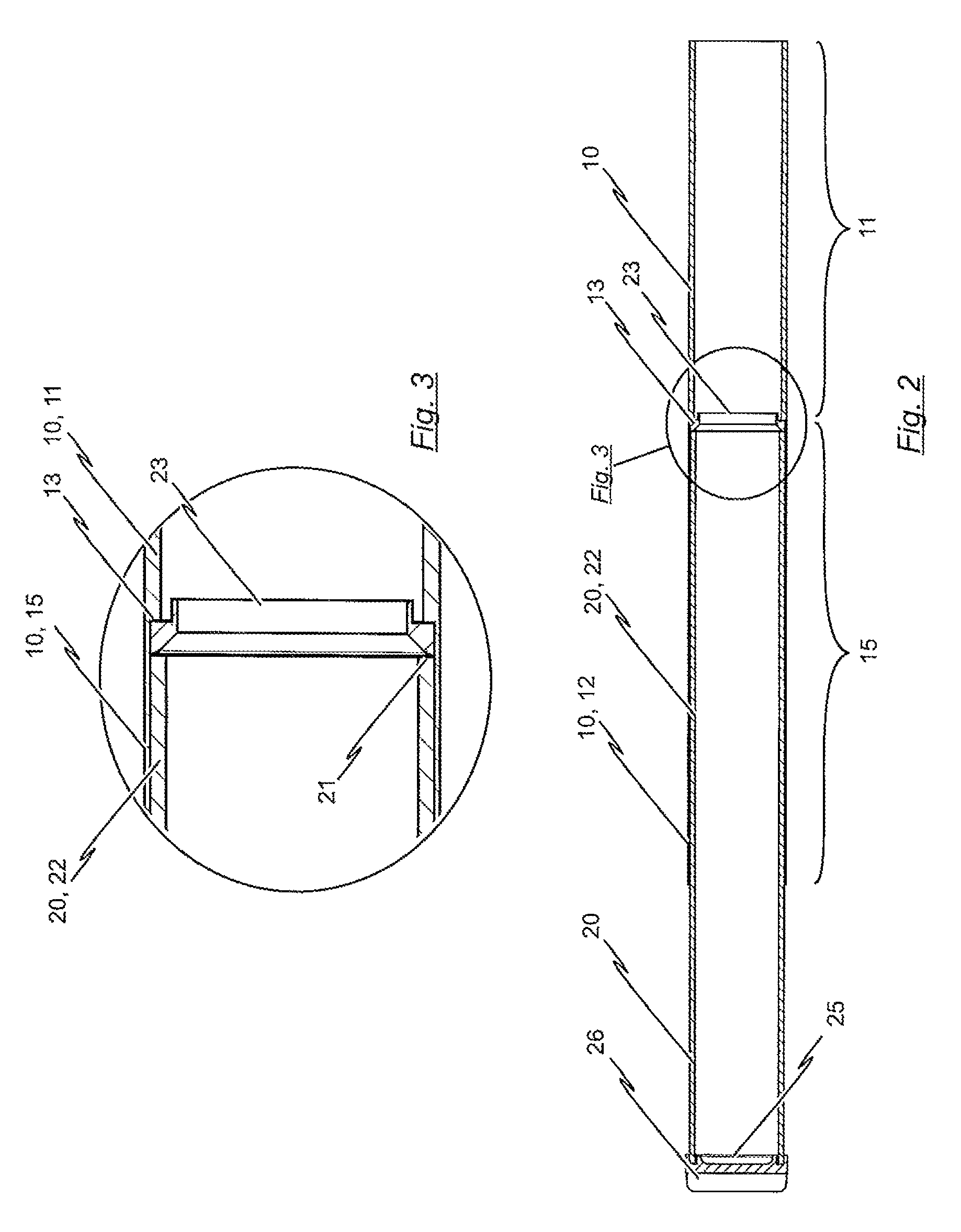
[0035]In FIG. 2, the energy-absorbing device shown in FIG. 1 is shown in a view in longitudinal section. It can be seen from this view that the mating member 20 is in the form of a piston and that that region 12 of the energy-absorbing member 10 which is adjacent the mating member 20 is in the form of a cylinder. That region 22 of the mating member 20 in the form of a cylinder which is adjacent the energy-absorbing member 10 is held telescopically by that region 12 of the energy-absorbing member 10 which is in form of a cylinder.

[0036]The construction and operation in particular of the embodiment of the energy-absorbing device ...


PUM


Abstract

An energy-absorbing device in the form of a safety device against shock loads for a track-borne vehicle includes an energy-absorbing member and a mating member. The mating member co-operates with the energy-absorbing member in such a way that, if a critical shock force applied to the energy-absorbing device is exceeded, the mating member and the energy-absorbing member move relative to one another, towards one another, while at the same time absorbing at least some of the shock energy which is applied to the energy-absorbing device. To enable the overall energy which can be dissipated by the energy-absorbing device to be increased in a way which is easy to implement, provision is made for the energy-absorbing member to have at least one energy-absorbing region made of fibrous composite material which, in the course of the movement of the mating member relative to the energy-absorbing member, is at least partly reduced to fibers non-ductilely.

Description

BACKGROUND OF THE INVENTION[0001]1. Field of the Invention[0002]The invention relates to an energy-absorbing device, in particular in the form of safety device against shock loads for a track-borne vehicle, the energy-absorbing device having an energy-absorbing member and a mating member which co-operates with the energy-absorbing member in such a way that, if a critical shock force applied to the energy-absorbing device is exceeded, the mating member and the energy-absorbing member move relative to one another, towards one another, while at the same time absorbing at least some of the shock energy which is applied to the energy-absorbing device.[0003]2. Prior Art[0004]It is known for track-borne vehicles, such as rail-borne vehicles for example, to be fitted with a safety device against shock loads which has at least one energy-absorbing device the purpose of which is to at least partly dissipate the shock energy which occurs if the vehicles hits an obstacle. An energy-absorbing de...

Claims


Application Information

Patent Timeline
Patent Type & Authority Patents(United States)
IPC IPC(8): F16F7/12
CPCB61G11/16F16F7/12F16F2224/02
Inventor BEIKA, UWEENDE, SASCHA
Owner VOITH PATENT GMBH
Features
  • R&D
  • Intellectual Property
  • Life Sciences
  • Materials
  • Tech Scout
  • Unparalleled Data Quality
  • Higher Quality Content
  • 60% Fewer Hallucinations
Learn More