Retaining element and heat shield element for a heat shield and combustion chamber provided with a heat shield

a technology of heat shield and heat shield element, which is applied in the direction of machines/engines, lighting and heating apparatus, furnaces, etc., can solve the problems of increasing the barrier air required to adequately block the large gaps, not being securely fixed in the axial direction of the combustion chamber, and increasing the penetration of hot gas into the gaps

Inactive Publication Date: 2012-01-31
SIEMENS AG
View PDF11 Cites 19 Cited by
  • Summary
  • Abstract
  • Description
  • Claims
  • Application Information

AI Technical Summary

Benefits of technology

[0011]The projection of the inventive retaining element allows engagement in a recess present in the heat shield element, as a result of which the heat shield element can be secured against displacement in a direction parallel to the peripheral surface provided with the groove.
[0016]An inventive combustion chamber, which can be configured for example as a gas turbine combustion chamber and in particular as an axially symmetrical gas turbine combustion chamber or an inventive flame tube, comprises a support structure and a heat shield secured to the support structure. The heat shield is made up of a number of inventive heat shield elements and a number of inventive retaining elements. The heat shield elements are disposed by means of the retaining elements on the support structure to provide cover with gaps left between, with the projections of the retaining elements engaging with the material recesses of the heat shield elements. This engagement allows the heat shield elements to be protected against displacement in relation to the support structure. Fixing of the heat shield elements in the axial direction can be effected in particular in axially symmetrical combustion chambers or flame tubes, in which the heat shield elements are fixed in the peripheral direction by engagement of the retaining elements in the grooves.

Problems solved by technology

They are however not securely fixed in the axial direction of the combustion chamber, as an axial fixing system is not provided.
If the tolerances are distributed unfavorably, for example if all the heat shield elements are at the lower tolerance band, the gaps between adjacent heat shield elements can increase due to displacement of the heat shield elements in the axial direction, resulting in increased penetration of hot gas into the gaps.
If large gaps, which can occur due to axial displacement, have to be taken into account, this increases the barrier air required to block the large gaps adequately.
The increased temperature gradient in turn results in increased crack formation in the area of the edges of the ceramic heat shield elements and also in the cracks being longer than with a smaller temperature gradient.

Method used


Image

  • Retaining element and heat shield element for a heat shield and combustion chamber provided with a heat shield
  • Retaining element and heat shield element for a heat shield and combustion chamber provided with a heat shield
  • Retaining element and heat shield element for a heat shield and combustion chamber provided with a heat shield

Examples


Embodiment Construction

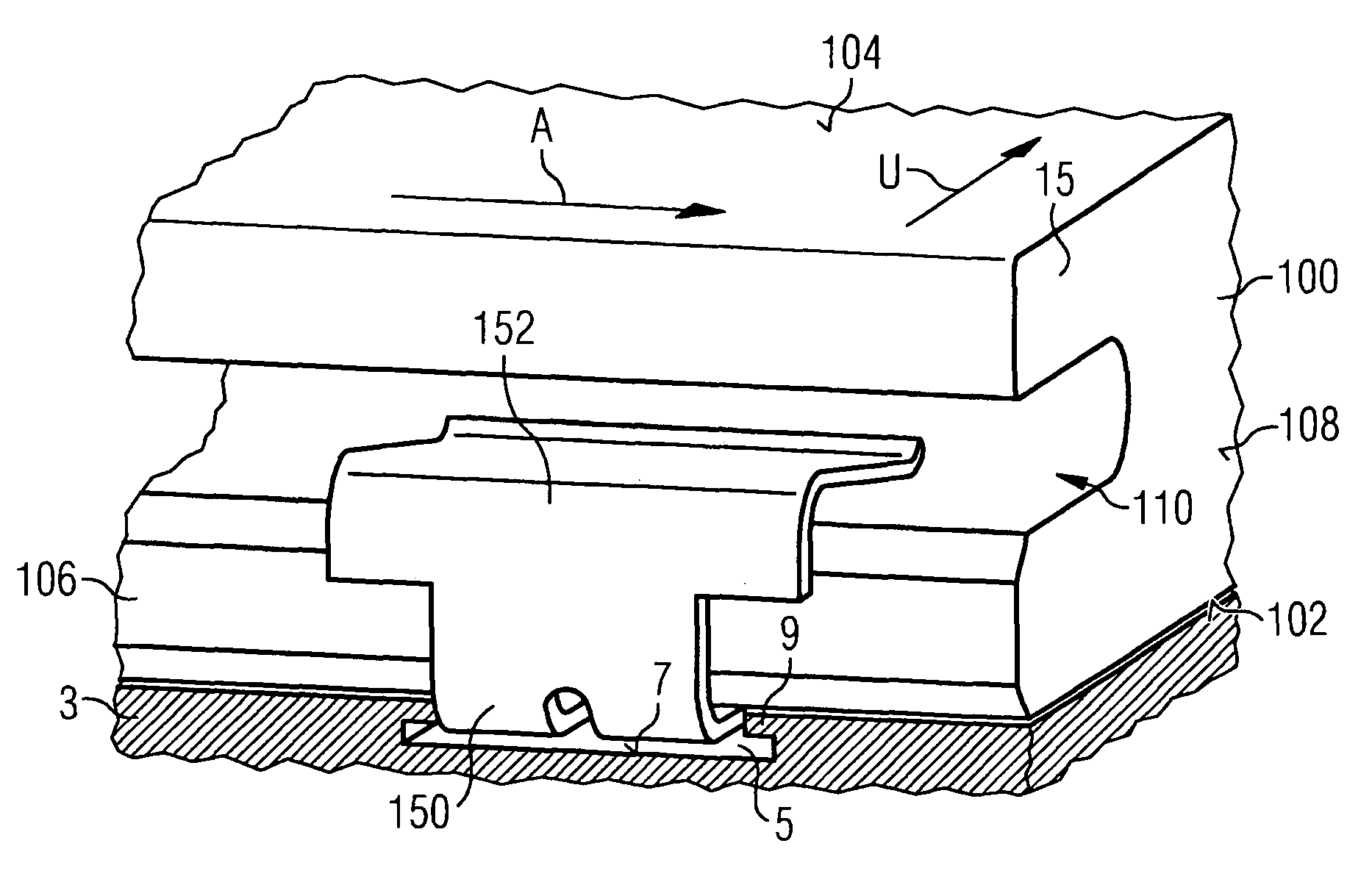
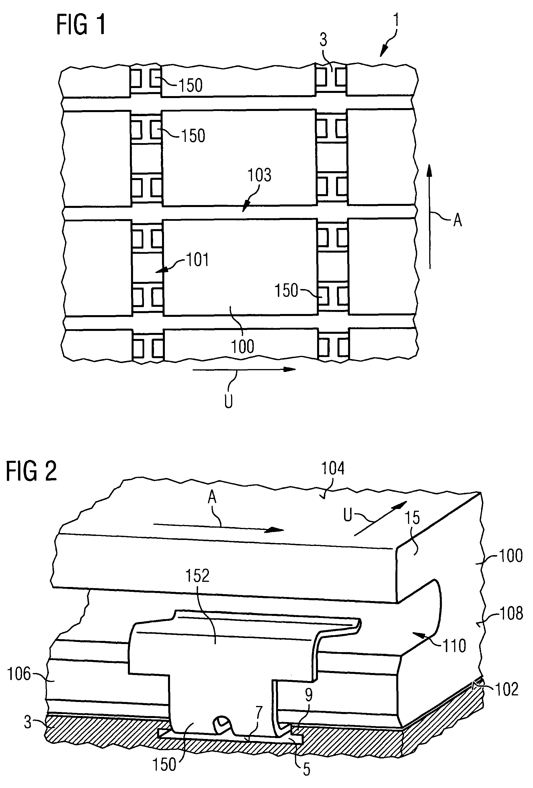
[0030]FIG. 1 shows a section from an axially symmetrical gas turbine combustion chamber as an exemplary embodiment of an inventive combustion chamber. The axial direction is indicated by the arrow marked A in FIG. 1.

[0031]The combustion chamber 1 has a support structure 3 and a heat shield secured to the support structure 3, made up of a number of heat shield elements 100, which are retained on the support structure 3 by means of retaining elements 150. The heat shield elements 100 are disposed on the support structure 3 to provide cover, leaving gaps 101, 103 between, in the peripheral direction U and axial direction A of the combustion chamber, with the retaining elements 150 projecting into the gaps 101 running in the axial direction A. To block the gaps to prevent the ingress of hot gas, said gaps can be flushed with pressurized air.

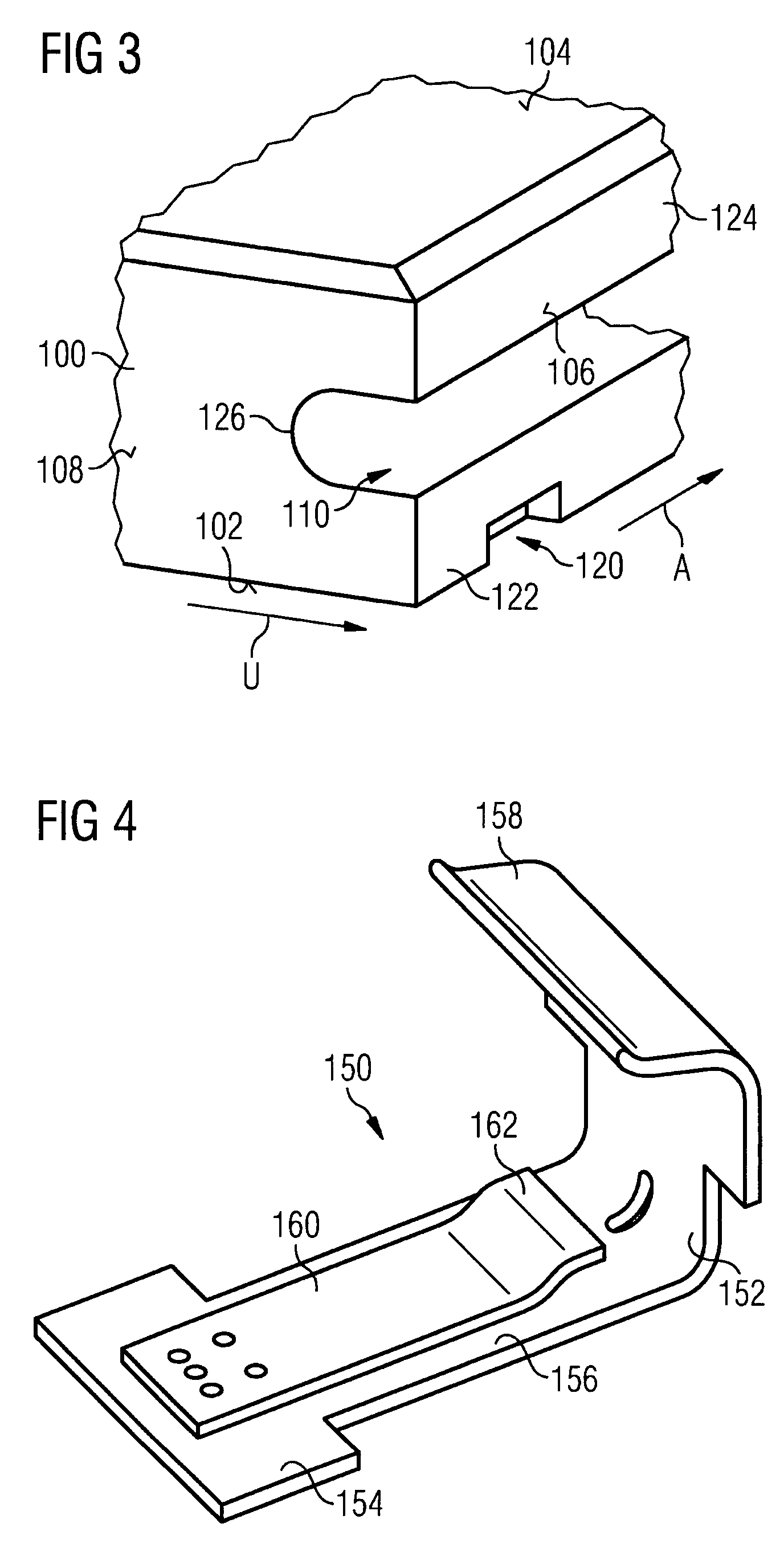
[0032]A heat shield element 100 and a retaining element 150 securing the heat shield element to the support structure 3 are shown in detail in FIG. ...


PUM


Abstract

A retaining element for retaining a heat shield element on a support structure comprises at least one fixing section adapted to fix the retaining element to the support structure and at least one retaining section adapted to engage with an engaging groove present on a periphery of the heat shield element. A projection is arranged on the retaining element in such a manner that it projects in the direction of the heat shield element when retaining a heat shield element.

Description

CROSS REFERENCE TO RELATED APPLICATIONS[0001]This application is the US National Stage of International Application No. PCT / EP2006 / 061623, filed Apr. 18, 2006 and claims the benefit thereof. The International Application claims the benefits of European application No. 05008510.9 filed Apr. 19, 2005, both of the applications are incorporated by reference herein in their entirety.FIELD OF INVENTION[0002]The present invention relates to retaining elements and heat shield elements for constructing a heat shield secured to a support structure and a combustion chamber with a support structure and heat shield secured thereto.BACKGROUND OF THE INVENTION[0003]Heat shields are used for example in combustion chambers or flame tubes, which may be part of a furnace, a hot gas duct or a gas turbine and in which a hot medium is produced or ducted. Gas turbine combustion chambers which are subject to a high level of thermal loading for example are therefore lined with a heat shield to protect again...

Claims


Application Information

Patent Timeline
Patent Type & Authority Patents(United States)
IPC IPC(8): F02C1/00F02G3/00
CPCF23M5/04F23R3/007F27D1/0033F27D1/14E04F2201/0517F23M2900/05002
Inventor FISCHER, MARCUSTERTILT, MARCVONNEMANN, BERND
Owner SIEMENS AG
Why Eureka
Try Eureka