
Inflatable wing flight vehicle

a technology of inflatable wings and flight vehicles, which is applied in the field of flight vehicles, can solve the problems of limited maneuverability and control problems of blimps, and achieve the effect of thin atmosphere and improved lift characteristics

Inactive Publication Date: 2012-01-31
SHAW DONALD ORVAL
View PDF14 Cites 18 Cited by
  • Summary
  • Abstract
  • Description
  • Claims
  • Application Information

AI Technical Summary

Benefits of technology

The inflatable airfoil configuration enables the aircraft to maintain extended flight periods, navigate diverse Martian terrain, and perform precision operations, while also being adaptable for high-altitude Earth missions, offering improved lift characteristics and versatility in various atmospheric conditions.

Problems solved by technology

Parachutes can have some maneuverability, but the maneuverability is generally limited.
Blimps can also have control issues when compared to airfoils.

Method used


Image

  • Inflatable wing flight vehicle
  • Inflatable wing flight vehicle
  • Inflatable wing flight vehicle

Examples


Embodiment Construction

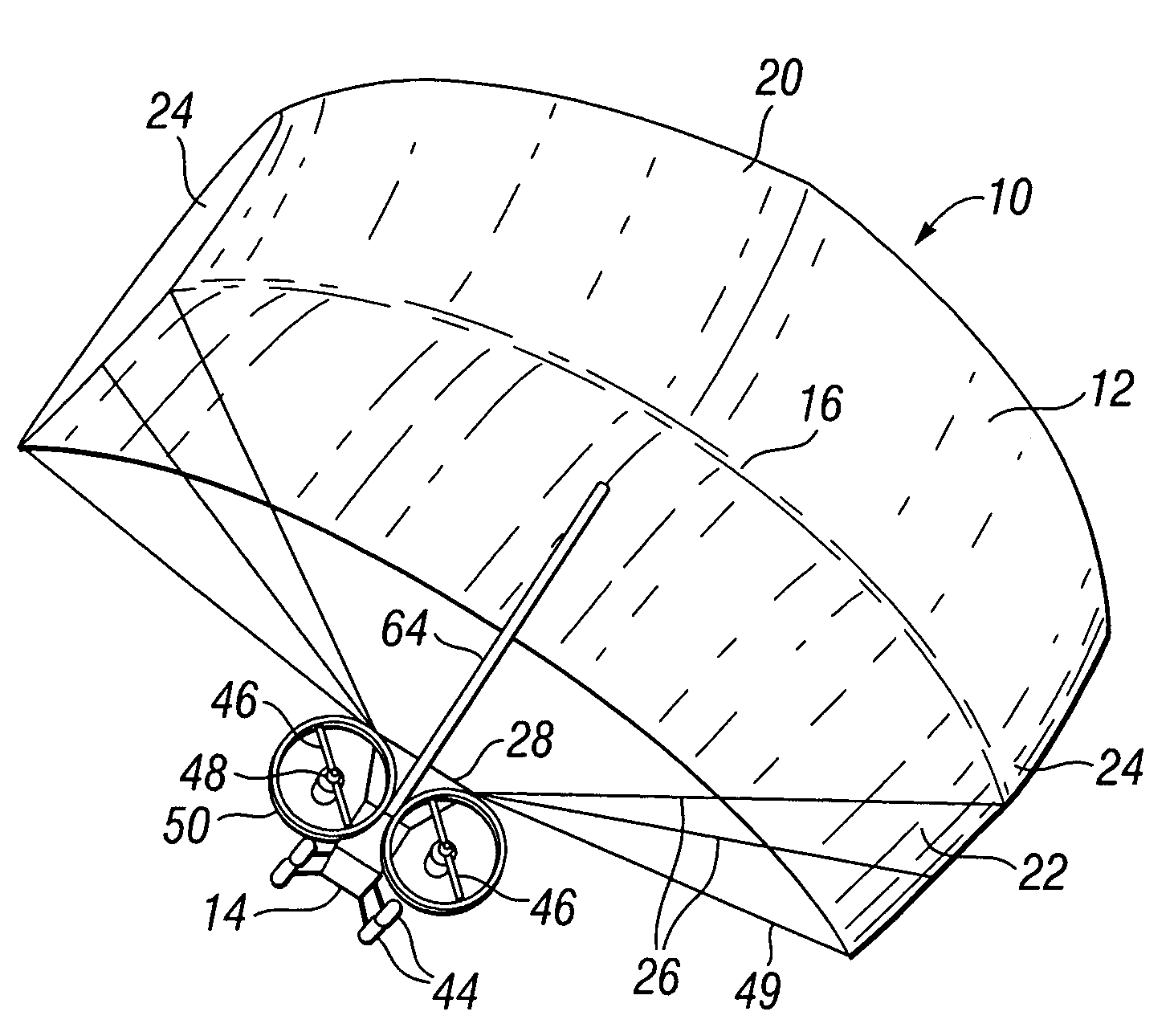
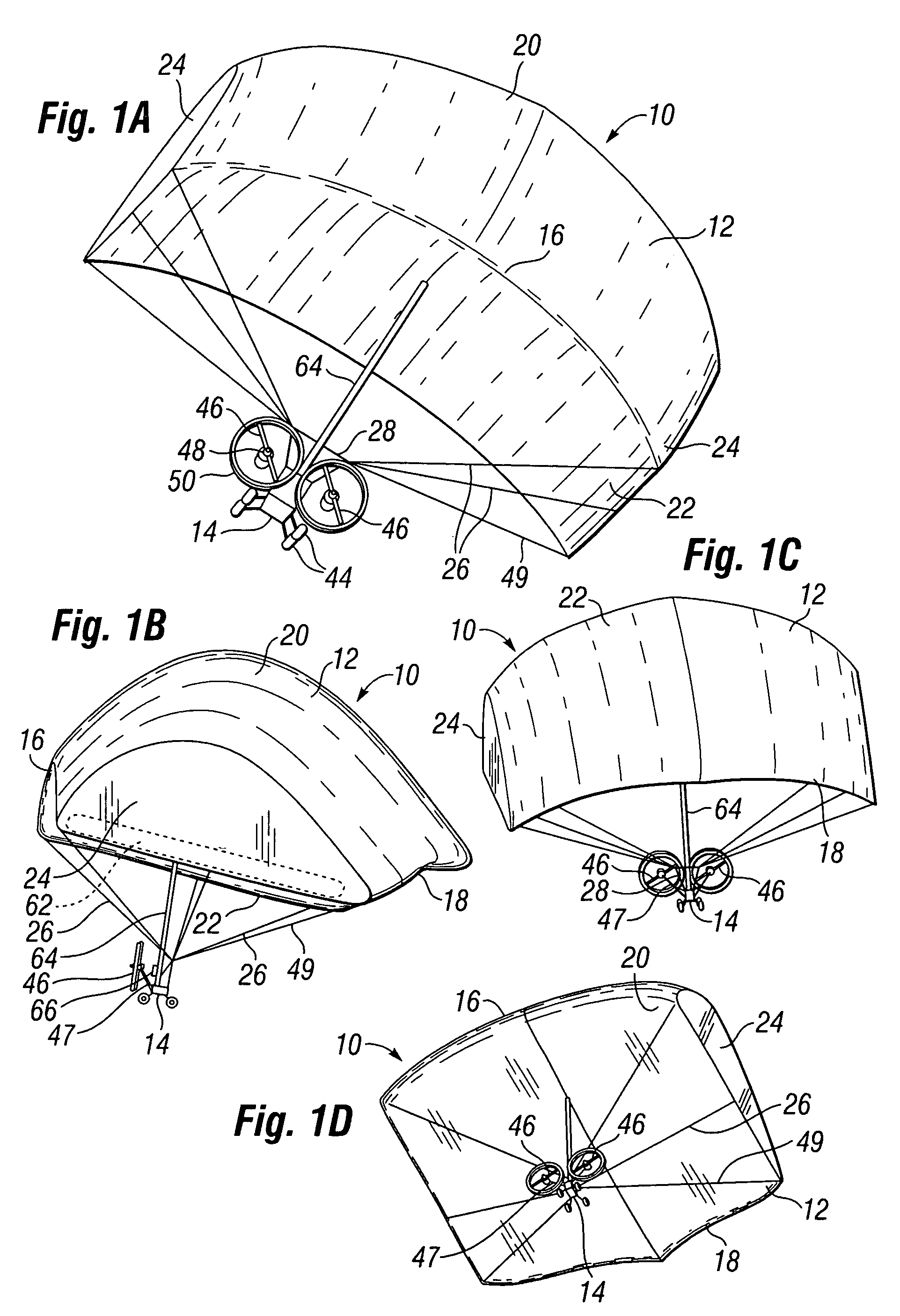
[0039]With reference to FIGS. 1A-1D, an air vehicle 10 according to the invention has an inflatable airfoil 12 secured to a base unit 14. The airfoil 12 has a leading edge 16, trailing edge 18, top 20, bottom 22, and sides 24. The airfoil 12 is secured to the base unit 14 via connections such as canopy lines 26 and risers 28.

[0040]The base unit 14, which is also depicted in FIG. 3 in greater detail, has a front 30, back 32, bottom 34, top 36, and sides 40, and includes a main body 42, wheels 44, propellers 46, motor 48, optional propeller cage or shroud 50, solar panels 52, batteries 54, scientific payloads 56, drill 58, and communication antenna 60. The wheels 44 may be inflatable wheels, which could be inflated with surrounding atmosphere, residual gases left over from the manufacturing and assembly process on Earth, and / or other gases such as the lifting gas used for the airfoil, and may be inflated prior to entering the Martian atmosphere, during atmospheric entry, or after such...


PUM


Abstract

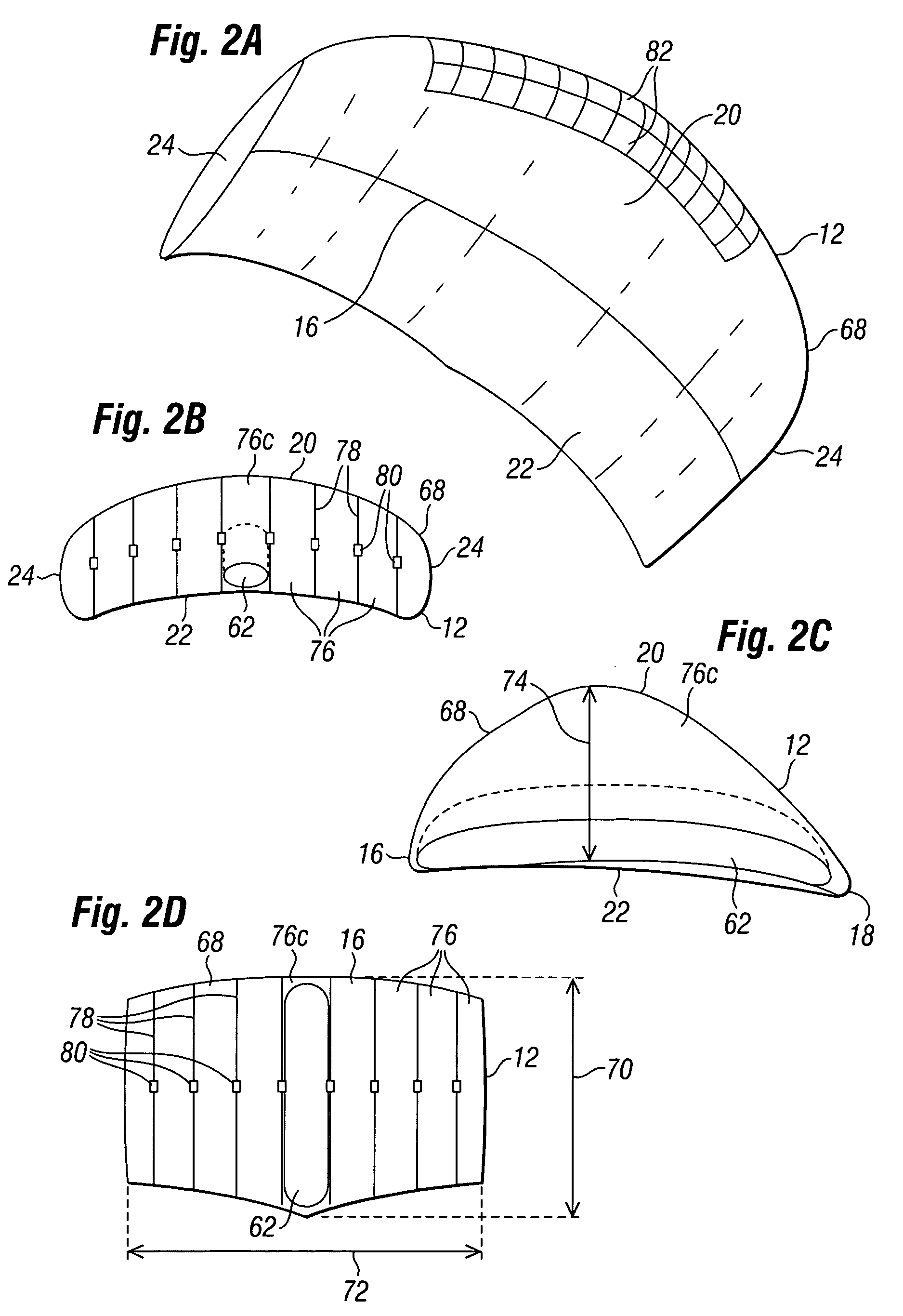
The invention is an aircraft having an inflatable wing connected to a base unit, with the inflatable wing inflated with a lifting gas such as helium. The inflatable wing has a series of cell structures, and may be configured with ballonets to selectively introduce and expel outside air within the inflatable wing to vary the buoyancy and / or airfoil properties of the inflatable wing. The aircraft is particularly useful at low speeds and in thin atmospheres (such as at high Earth altitudes and on Mars), and can be used for interplanetary missions to explore planetary bodies, such as moons and planets, having atmospheres.

Description

RELATED APPLICATIONS[0001]The present application claims priority from U.S. provisional patent application Ser. No. 60 / 934,349, filed on Jun. 12, 2007 and entitled “Mars Flight Vehicle,” the contents of which are expressly incorporated herein in their entirety.FIELD OF THE INVENTION[0002]The present invention relates to a flight vehicle, and more particularly to a flight vehicle having an inflatable airfoil configured to operate in relatively low atmospheric conditions such as may be encountered on Mars, and also for potential atmospheric entry in interplanetary missions.BACKGROUND OF THE INVENTION[0003]Various aircraft using static lift (i.e., buoyancy) or active lift (such as that provided by airfoils) are known in the art. Lighter-than-air aircraft include balloons and airships, which use static lift for all or much of their lifting capacity. Heavier-than-air aircraft include airplanes and helicopters, both of which use active lift provided by airfoils (including rotors having li...

Claims


Application Information

Patent Timeline
Patent Type & Authority Patents(United States)
IPC IPC(8): B64D17/80B64D17/00B64G1/10
CPCB64C3/30B64C31/036B64D27/24B64B2201/00B64G2001/1071Y02T50/62Y02T50/60B64G1/1071
Inventor SHAW, DONALD ORVAL
Owner SHAW DONALD ORVAL
Learn More