Subsoil drainage system

a drainage system and subsoil technology, applied in irrigation ditches, agriculture, construction, etc., can solve the problems of limited design configuration of current subsoil based absorption system products, lack of system flexibility and installation adaptability, and difficulty in conventional systems to provide the increased bottom area and/or sidewall area required in some designs

Active Publication Date: 2012-01-31
DONLIN JAMES M
View PDF14 Cites 21 Cited by
  • Summary
  • Abstract
  • Description
  • Claims
  • Application Information

AI Technical Summary

Benefits of technology

[0008]The support pipe provides structural integrity and in some embodiments internal fluid distribution i

Problems solved by technology

Current subsoil based absorption system products are limited in their design configuration, lack system flexibility and installation adaptability.
It is also difficult for conventional systems to provide the increased bottom area and/or sidewall area required in some designs.
Engineers, absorp

Method used


Image

  • Subsoil drainage system
  • Subsoil drainage system
  • Subsoil drainage system

Examples


Embodiment Construction

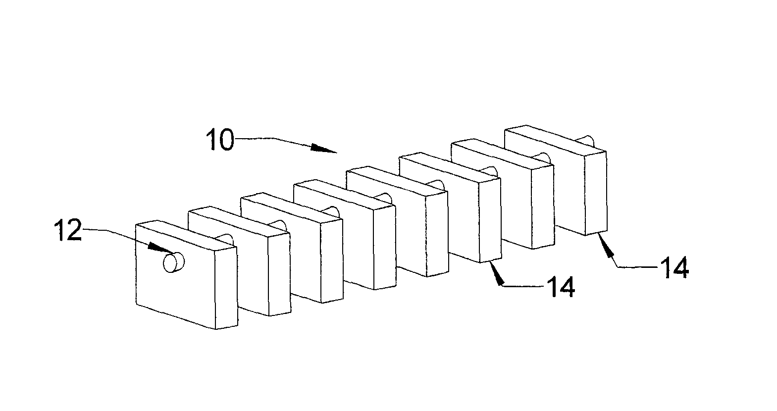
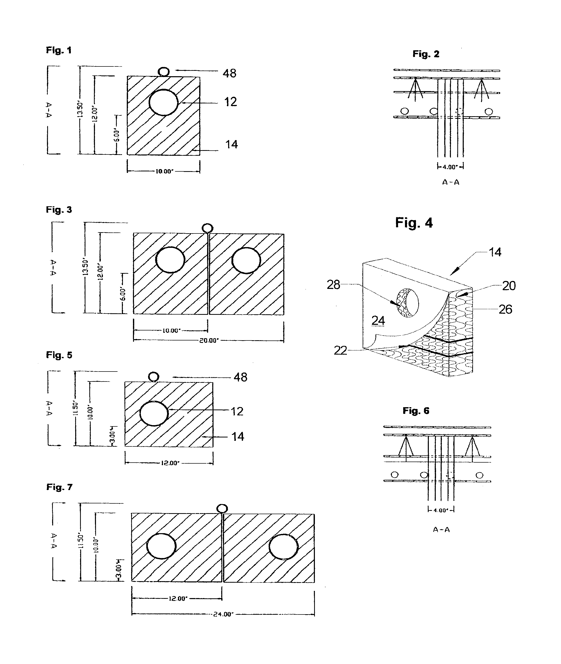
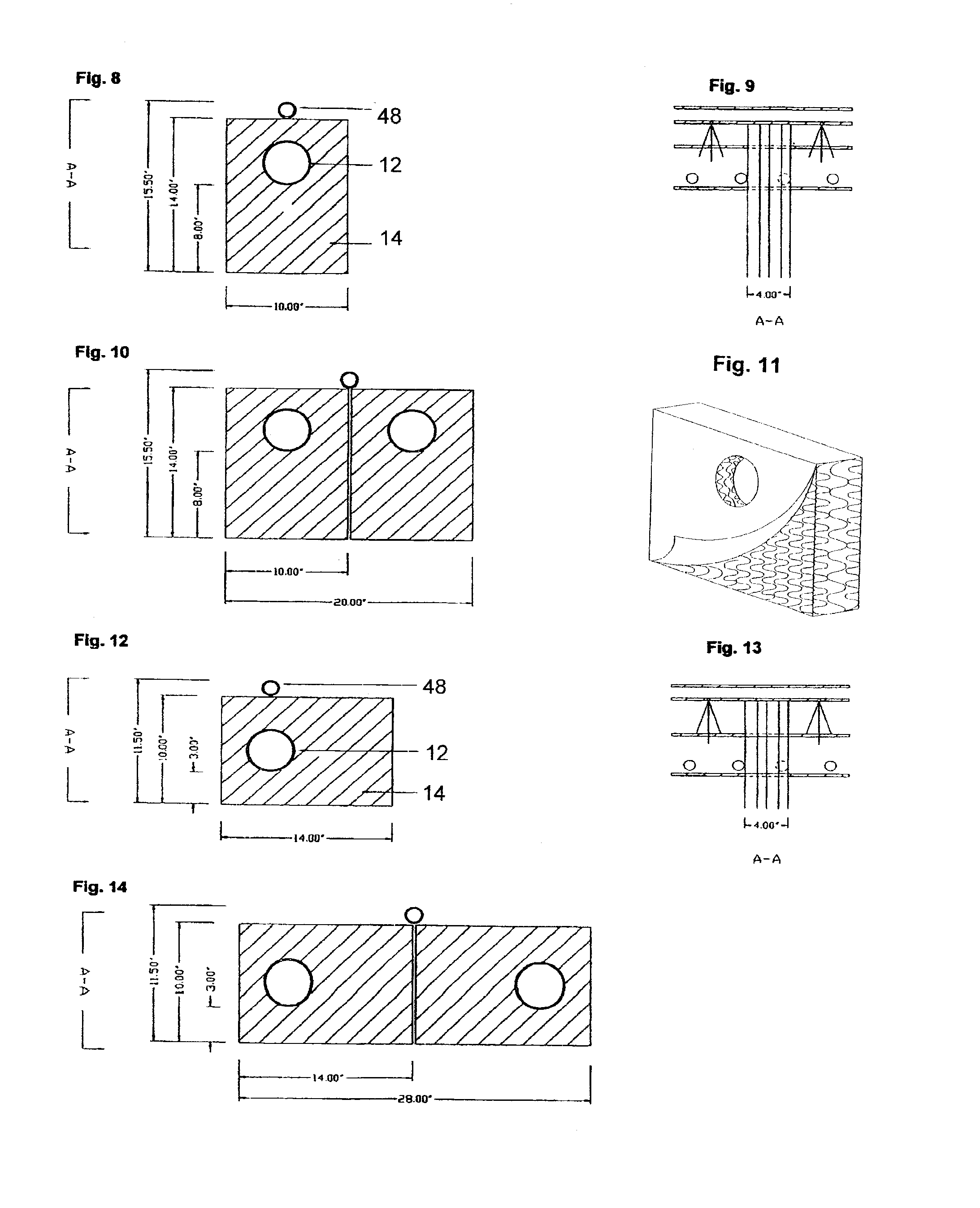
[0066]With reference to FIG. 17, a PME unit 10 is formed by combining a support pipe 12 with one or more support modules, each 14 so that the support modules 14 are attached to the support pipe 12.

[0067]With reference to FIG. 4, each support module 14 is constructed of any suitable sheet material of various widths and lengths. Preferably the sheet material is a polymeric material. Recycled high impact polystyrene having a thickness of 0.24 inches has been found suitable for use as a module sheet 20. The module sheets 20 are configured into flat sheets and / or egg carton shaped cuspated core sheets. Cuspated sheets are described in U.S. Pat. No. 4,880,333 the contents of which are incorporated by reference. The cuspated core sheets, alone or in combination with flat sheets are aligned in face to face orientation and joined together, for example with bands 22, to form the support module 14. Commercially available plastic banding material has been found suitable for banding the aligned ...


PUM


Abstract

Disclosed is a PME unit comprising a support pipe disposed within an aperture of a support module. Advantageously the support pipe is disposed within the apertures of a plurality of spaced support modules. The PME unit is placed within an excavation to provide a subsoil fluid absorption system.

Description

CROSS REFERENCE TO RELATED APPLICATIONS[0001]This application claims the benefit of U.S. Provisional Application No. 60 / 657,308, filed Feb. 28, 2005 and U.S. Provisional Application No. 60 / 741,502, filed Dec. 1, 2005, the contents of each of which are incorporated by reference herein.FIELD OF THE INVENTION[0002]The present invention relates generally to subsoil fluid absorption and drainage systems.BACKGROUND OF THE INVENTION[0003]Conventional subsoil fluid absorption systems are comprised of trenches or excavations filled with small rock aggregate and overlaid with a perforated pipe. The pipe may be overlaid with a geotextile fabric and / or more rock aggregate. Soil is placed over the aggregate and perforated pipe to fill the trench to the adjoining ground level. In use, fluid flows through the pipe and out the perforations. Fluid is held within cavities in the aggregate until it can be absorbed into the soil. Other conventional systems use hollow plastic chambers placed beneath gro...

Claims


Application Information

Patent Timeline
IPC IPC(8): E02B11/00
CPCE02B11/005
Inventor DONLIN, JAMES M.
Owner DONLIN JAMES M
Why Eureka
Try Eureka