
Spring connector and terminal device

a technology of spring connector and terminal device, which is applied in the direction of coupling device connection, electrically conductive connection, instruments, etc., can solve the problems of low reliability of contact, reset of setting content of cellular phone terminal, and low reliability of contact with spring connector. achieve good electrical connection state and reliable electrical conduction with each other

Inactive Publication Date: 2012-01-31
SONY ERICSSON MOBILE COMM AB
View PDF10 Cites 5 Cited by
  • Summary
  • Abstract
  • Description
  • Claims
  • Application Information

AI Technical Summary

Benefits of technology

"The present invention provides a spring connector with improved contact reliability and stability of electrically conductive state. The connector includes an inner conductor and an outer conductor, with the inner conductor having a small-diameter portion, a large-diameter portion, and a resilient portion. The large-diameter portion and the resilient portion of the inner conductor are accommodated in the hole of the outer conductor while the small-diameter portion protrudes from an end of the hole. This structure functions as a plunger, and the plunger is pushed up by the resilient portion integrated to the large-diameter portion of the spring connector. The connector achieves a good electrical connection state and prevents instaneous cutoff, which can lead to unstable contact reliability."

Problems solved by technology

From the viewpoint of achieving stability of an electrically conductive state, such contacts have low contact reliability.
Therefore, the spring connector does not often stably function as a connector.
When the “instantaneous cutoff” occurs, problems result in that, for example, setting content of the cellular phone terminal is reset and a portion of data is lost.

Method used


Image

  • Spring connector and terminal device
  • Spring connector and terminal device
  • Spring connector and terminal device

Examples


second embodiment

[0031]5. Function of the spring connector

[0032]6. Method of producing a modification of an embodiment (FIGS. 8a to 8c and 9a to 9c)

1. Exemplary Structure of Spring Connector

first embodiment

[0033]the present invention will hereunder be described with reference to FIGS. 1 to 6.

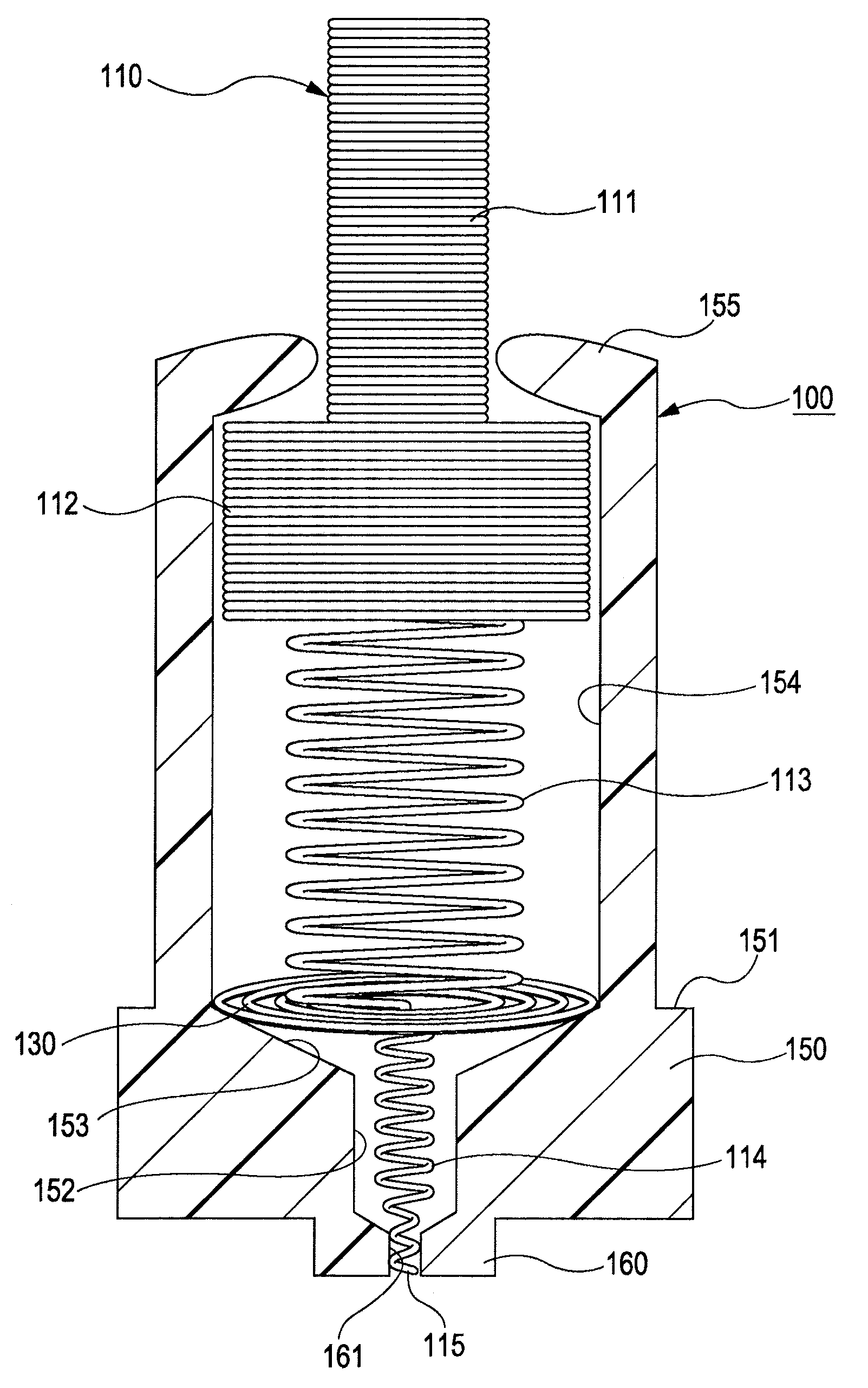
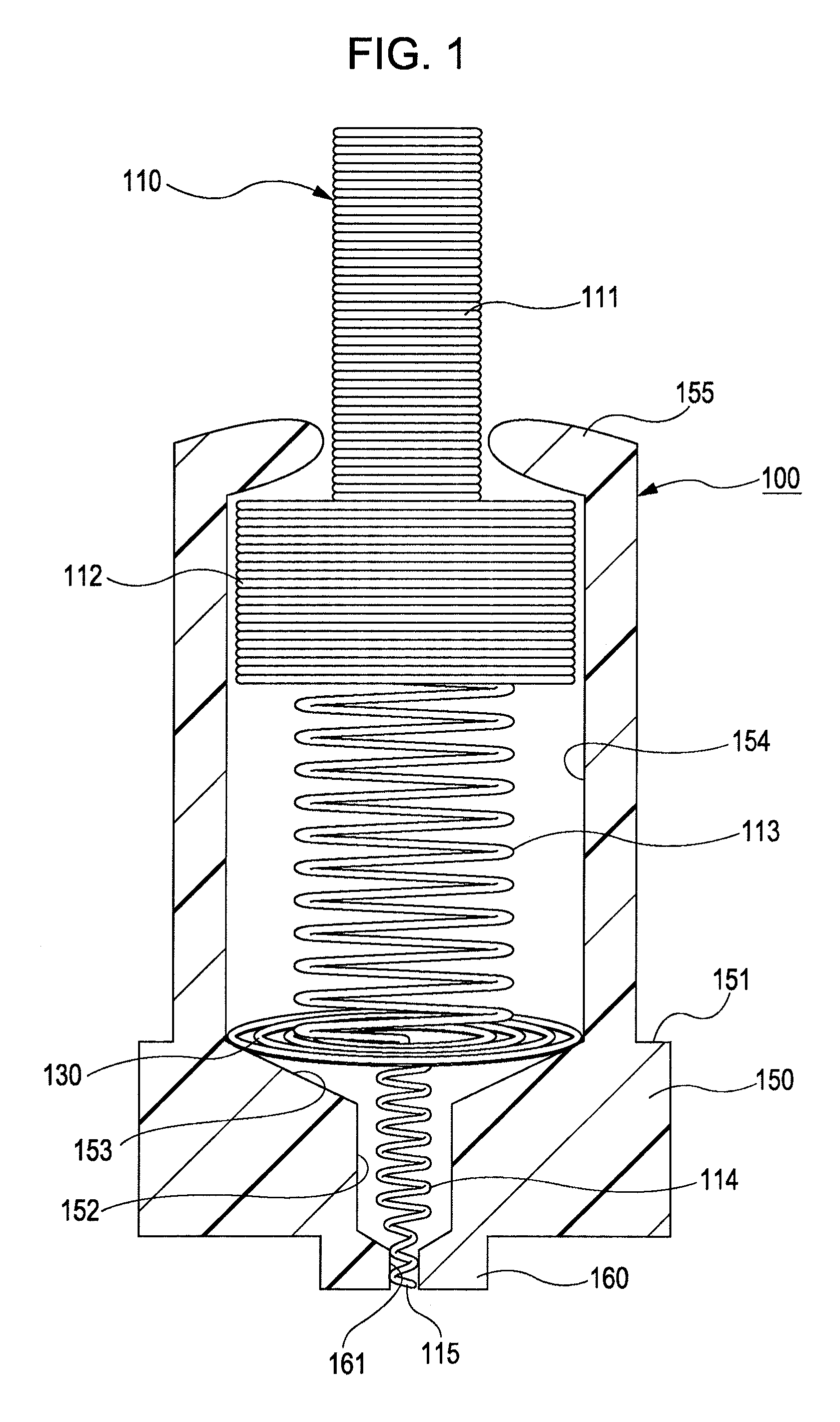
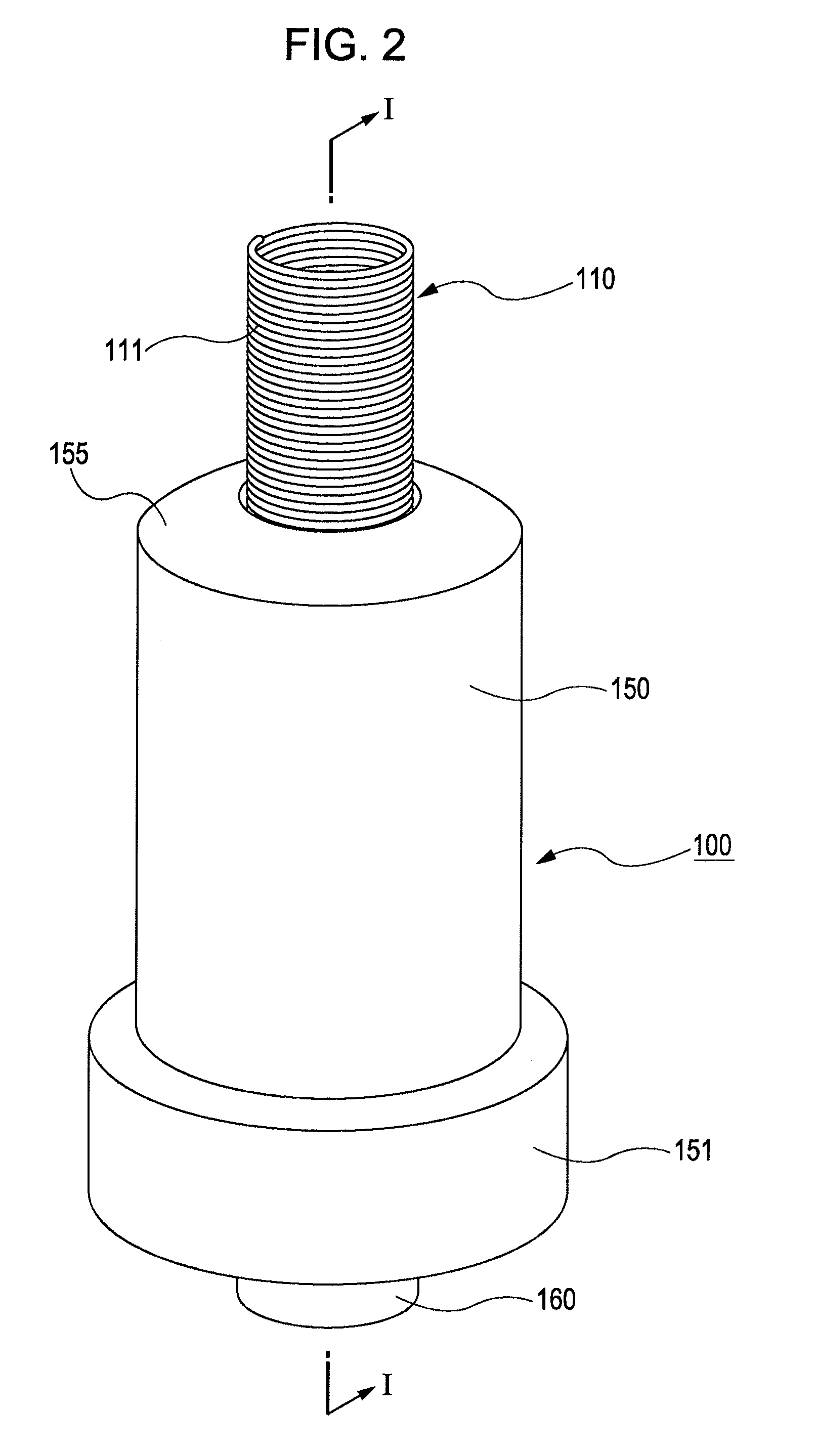
[0034]FIGS. 1 and 2 each show the shape of a spring connector 100 according to the embodiment. FIG. 2 is a perspective view of the overall shape of the spring connector 100. FIG. 1 is a vertical sectional view taken along line I-I in FIG. 2. When a vertical direction is indicated in the following description, this vertical direction indicates a positional relationship shown in FIGS. 1 and 2.

[0035]As shown in FIG. 1, the spring connector 100 includes an inner conductor, formed of a conductive material, and an outer conductor, accommodating the inner conductor. That is, a pin-provided spring 110, formed of a conductive material (such as a metal), is accommodated in a tube 150, formed of a conductive material (such as a metal) and having a hollow inner side. The pin-provided spring 110 functions as a plunger and as a resilient member (spring). A detailed structure of the pin-provided spring110 will b...


PUM


Abstract

A spring connector includes an inner conductor and an outer conductor. The inner conductor is formed of a conductive material, and has a small-diameter portion, a large-diameter portion, and a resilient portion axially disposed so as to be integrally and continuously formed with each other. The outer conductor is formed of a conductive material, and is provided with a hole having a predetermined inside diameter. The outer conductor accommodates the large-diameter portion and the resilient portion in the hole while the small-diameter portion protrudes from an end of the hole.

Description

BACKGROUND OF THE INVENTION[0001]1. Field of the Invention[0002]The present invention relates to a suitable spring connector used in, for example, a battery terminal of a cellular phone terminal, and to a terminal device including the spring connector.[0003]2. Description of the Related Art[0004]Hitherto, in an electronic device, such as a cellular phone terminal, a spring connector is mounted to a surface of a principle circuit board when an electrical component at, for example, a partial circuit board or a battery is connected to the principle circuit board. A spring connector is mounted by pushing a terminal electrode of the electrical component against a movable end that is urged by a spring. By this, electrical connection is achieved.[0005]FIGS. 10 and 11 each show an example of a related spring connector. FIG. 11 shows the entire structure of a spring connector 40. FIG. 10 is a vertical sectional view taken along line X-X in FIG. 11. As shown in FIG. 10, in the spring connecto...

Claims


Application Information

Patent Timeline
Patent Type & Authority Patents(United States)
IPC IPC(8): H01R13/24G01R1/067
CPCH01R13/2421
Inventor IKEGAMI, MASATOSHISUGIMORI, RIE
Owner SONY ERICSSON MOBILE COMM AB
Learn More