

Omnidirectional flat antenna and method of production
a flat antenna, omnidirectional technology, applied in the direction of antennas, antenna supports/mountings, coatings, etc., can solve the problem of not enabling satisfactorily receiving low-power magnetic waves, and achieve the effect of preventing shielding effects and reducing the volum
- Summary
- Abstract
- Description
- Claims
- Application Information
AI Technical Summary
Benefits of technology
Problems solved by technology
Method used
Image

Examples
Embodiment Construction
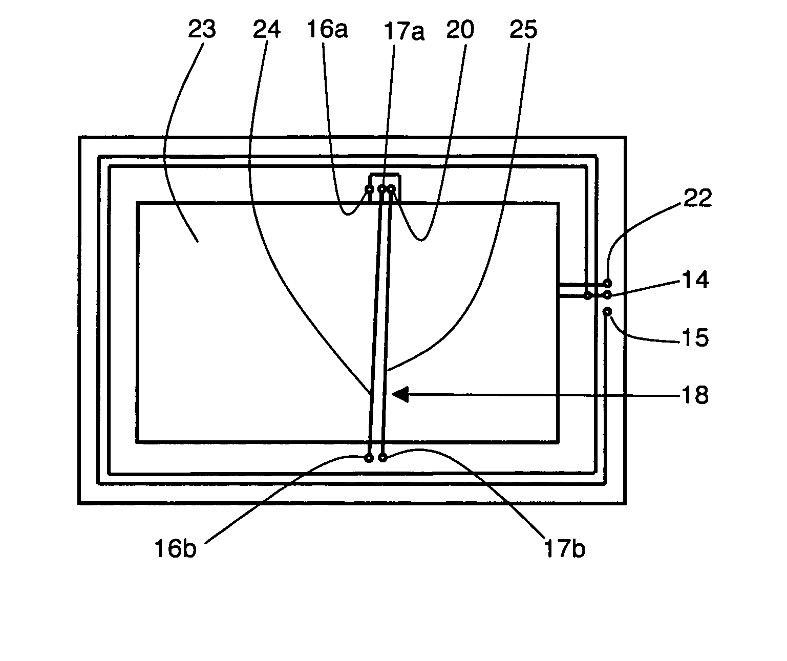
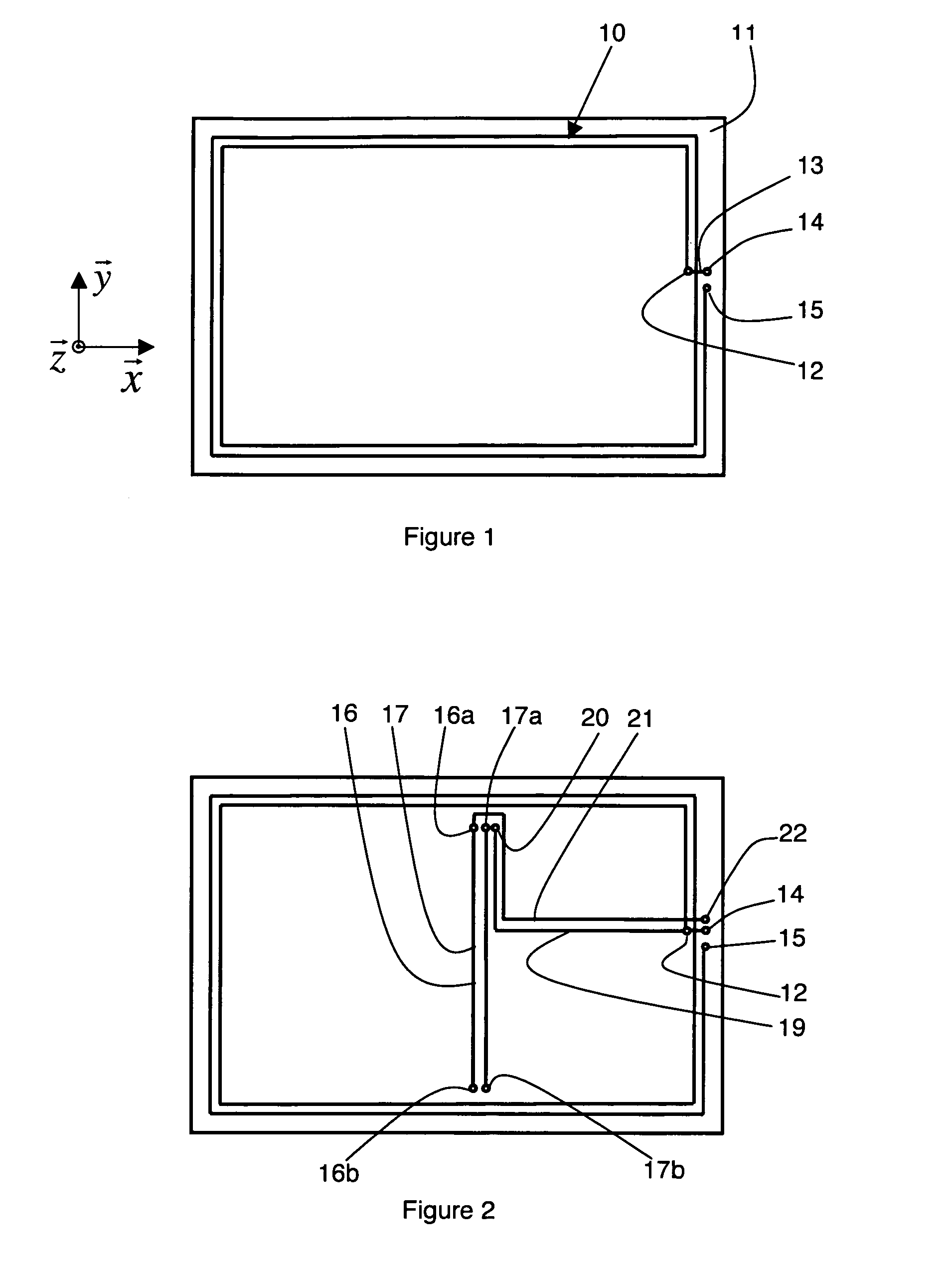
[0021]In the embodiment represented in FIG. 1, a first coil 10 is formed on a surface of a flat substrate 11 which can be made from any material, for example plastic, cardboard or paper. The first coil 10 is formed by a flat winding of spiral-wound conducting tracks, here with two substantially concentric turns, of rectangular shape. First coil 10 is made for example with silkscreened copper or by deposition of conducting ink. An orthogonal vector base ({right arrow over (x)}, {right arrow over (y)}, {right arrow over (z)}) is defined such that {right arrow over (x)} and {right arrow over (y)} are parallel to the axes of symmetry of first coil 10, and {right arrow over (z)} is perpendicular to the plane of substrate 11. The axis of first coil 10, i.e. the axis around which it is wound, is parallel to {right arrow over (z)}. First coil 10 is therefore practically only sensitive to the component along {right arrow over (z)} of an incident magnetic wave emitted by a remotely located re...
PUM
 Abstract
Description
Claims
Application Information