
Storage apparatus, and storage control method using the same

a storage apparatus and control method technology, applied in the field of storage apparatus, can solve the problems of low processing efficiency of the storage apparatus concerning write commands from the host computer, increase in processor load, and long time, and achieve the effects of reducing processing load, increasing processor load, and prolonging tim

Inactive Publication Date: 2012-01-31
HITACHI LTD
View PDF7 Cites 2 Cited by
  • Summary
  • Abstract
  • Description
  • Claims
  • Application Information

AI Technical Summary

Benefits of technology

This approach maintains data consistency across multiple secondary volumes without increasing the I / O load on the primary volume or processor, enhancing processing efficiency and reducing interference with other access operations.

Problems solved by technology

As a result, it may take a longer time for the storage apparatus to respond to the host computer to report the completion of the write processing, resulting in low processing efficiency in the storage apparatus concerning write commands from the host computers.
In particular, if one processor is used to execute write processing for both the primary volume and each of the several secondary volumes, the load on the processor increases considerably, causing a significant decrease in processing efficiency.
However, when copying the write data from the primary volume to the several secondary volumes, I / O access to the primary volume increases within the storage apparatus, which may affect other write / read access from the host computers targeting that primary volume.
Also, in storage apparatuses where processing on the front-end side and processing on the back-end side are executed by the same processor, i.e., so-called middle-range type storage apparatuses, if write processing is going to be executed for all of the secondary volumes simultaneously with the write processing for the primary volume, the load on the processor will inevitably increase.
So, in those middle-range type storage apparatuses, the number of secondary volumes that can form a synchronous pair with a particular primary volume has had to be limited.

Method used


Image

  • Storage apparatus, and storage control method using the same
  • Storage apparatus, and storage control method using the same
  • Storage apparatus, and storage control method using the same

Examples


Embodiment Construction

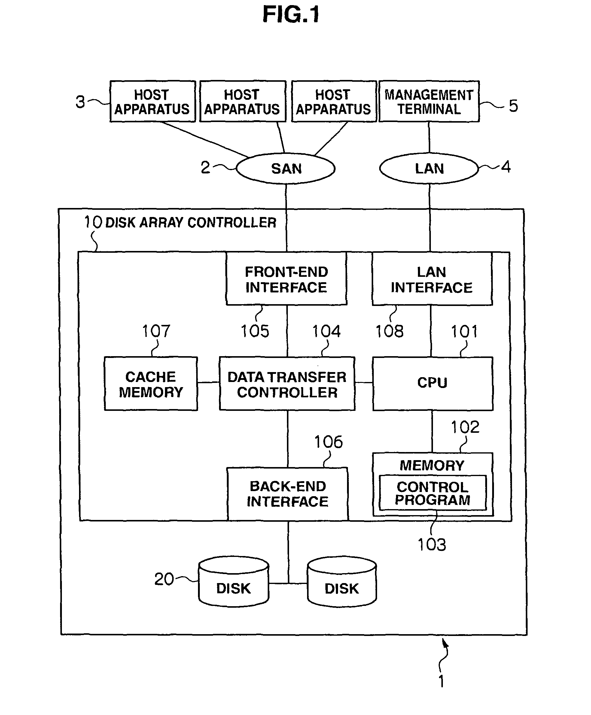
[0030]An example of a storage control system with a storage apparatus according to the present invention will be explained below. FIG. 1 is a hardware block diagram of a storage control system. The storage apparatus shown in FIG. 1 is a middle-range model as explained above, but obviously, a high-end model storage apparatus may also be used.

[0031]In FIG. 1, the storage apparatus 1 is configured to include a controller and a plurality of storage devices. A disk array controller 10 corresponds to the controller, and a plurality of hard disk drives 20 corresponds to the plural storage devices. The storage devices are not limited to hard disk drives, and they may also be semiconductor memory, such as flash memory chips.

[0032]The storage apparatus 1 is connected to several host apparatuses 3 (which correspond to host computers) via a SAN (Storage Area Network) 2, and is also connected to a management terminal 5 via a LAN (Local Area Network) 4. Using a control program 103 stored in memor...


PUM


Abstract

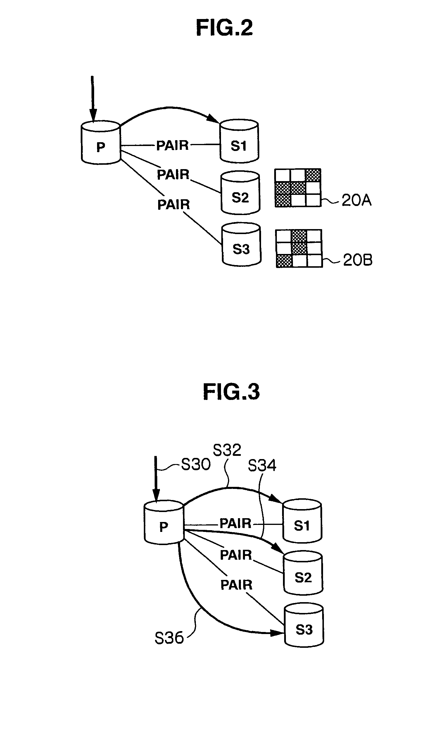
The present invention aims at providing a storage apparatus that does not increase the I / O load on a primary volume, even if there are several secondary volumes for which data consistency with the primary volume should be guaranteed. A storage apparatus writes write data for write access directed to a primary volume P to a secondary volume S1. A controller in the storage apparatus copies that write data from the secondary volume S1 to secondary volumes. S2 and S3 in background processing. The storage apparatus uses bitmaps to manage data in the secondary volume S1 shared by each of the secondary volumes S2 and S3.

Description

CROSS-REFERENCES TO RELATED APPLICATIONS[0001]This application relates to and claims priority from Japanese Patent Application No. 2007-000746, filed on Jan. 5, 2007, the entire disclosure of which is incorporated herein by reference.BACKGROUND[0002]1. Field of the Invention[0003]The present invention relates to a storage apparatus that provides a host apparatus with relevant controls for the host apparatus to store data in a storage unit. More specifically, the invention relates to a storage apparatus with a control function used when writing write data sent from a host apparatus to secondary volume(s).[0004]2. Description of Related Art[0005]A storage apparatus is an apparatus that is connected to host computer(s) and constitutes a storage control system, providing the host computer(s) with large-capacity storage areas. In that type of storage apparatus, a plurality of storage devices (e.g. hard disk drives) is installed in its case in arrays. The storage apparatus virtualizes its...

Claims


Application Information

Patent Timeline
Patent Type & Authority Patents(United States)
IPC IPC(8): G06F12/00G06F13/28G06F13/00
CPCG06F3/061G06F3/065G06F3/0683G06F11/2058G06F11/2066G06F2206/1012
Inventor NAGATA, KOJIKOBAYASHI, MASAAKI
Owner HITACHI LTD
Learn More