Device for implementing a cutting balloon intervention with IVUS monitoring

a technology of ivus monitoring and cutting balloon, which is applied in the field of devices for implementing cutting balloon interventions, can solve the problems of increased resting rate, additional process stage and additional cost of stents, coronary arteries, etc., and achieves the effect of convenient us

Active Publication Date: 2012-02-07
SIEMENS HEALTHCARE GMBH
View PDF27 Cites 13 Cited by
  • Summary
  • Abstract
  • Description
  • Claims
  • Application Information

AI Technical Summary

Benefits of technology

[0013]The object of the invention is therefore to configure a device of the type specified above, to provide an optimum device which is easy to use and which enables the point of intervention to be directly monitored, even during the vessel dilatation if necessary, without the tedious process of changing the various catheters.
[0015]The embodiment according to the invention provides an integrated module comprising a cutting balloon catheter with an IVUS catheter integrated therein, representing an optimum system for opening up complete vascular stenoses. The great advantage of the solution lies in the reduction in process stages and in the catheters used, and also in the reduction of x-rays applied. The IVUS system images provide important additional medical information with high resolution, particularly at close range over the plaque and the vascular wall. This means that the plaque can be identified, and can be removed by using the cutting balloon in the right location, and the success of the procedure can then be checked immediately without subjecting the patient to unnecessarily high levels of contrast media or x-rays. Furthermore, the risk of damage to the vascular wall is reduced.

Problems solved by technology

The compression of large quantities of plaque may result in damage to the inner vascular wall, leading to an increased restenosis rate.
A significant disadvantage of the method is the additional process stage and the additional costs for the stent.
The drawback of this method is that the coronary arteries are only shown in two dimensions and only the actual stenosis is shown on the x-ray image.
During the intervention it is difficult for medical staff to distinguish between plaque and vascular wall.
This increases the risk of incisions by the balloon blades being made in the wrong place, or of the incisions being too deep (resulting in “deep vessel wall injury”).
The introduction of an IVUS (intravascular ultrasound) catheter into the vessel enhances the imaging information, yet has the disadvantage that a relatively expensive catheter must also be inserted into the patient and must be removed from the vessel before the balloon catheter is inserted.

Method used


Image

  • Device for implementing a cutting balloon intervention with IVUS monitoring
  • Device for implementing a cutting balloon intervention with IVUS monitoring
  • Device for implementing a cutting balloon intervention with IVUS monitoring

Examples


Embodiment Construction

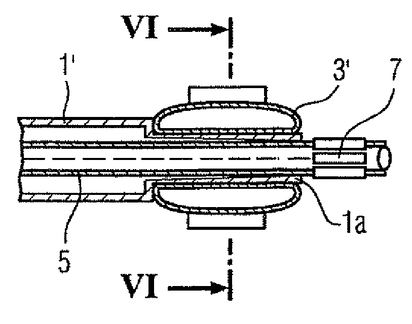
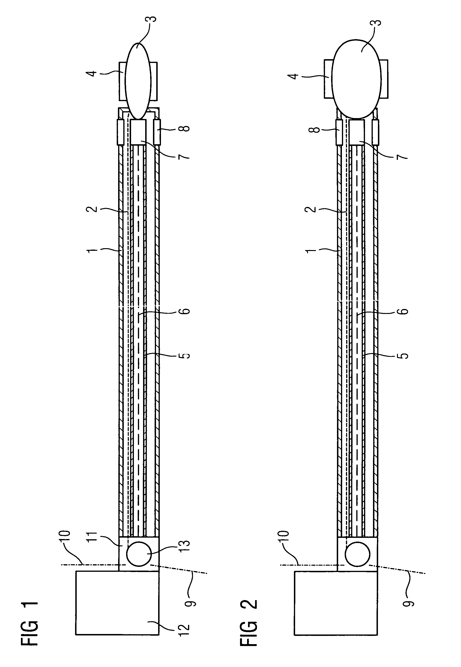
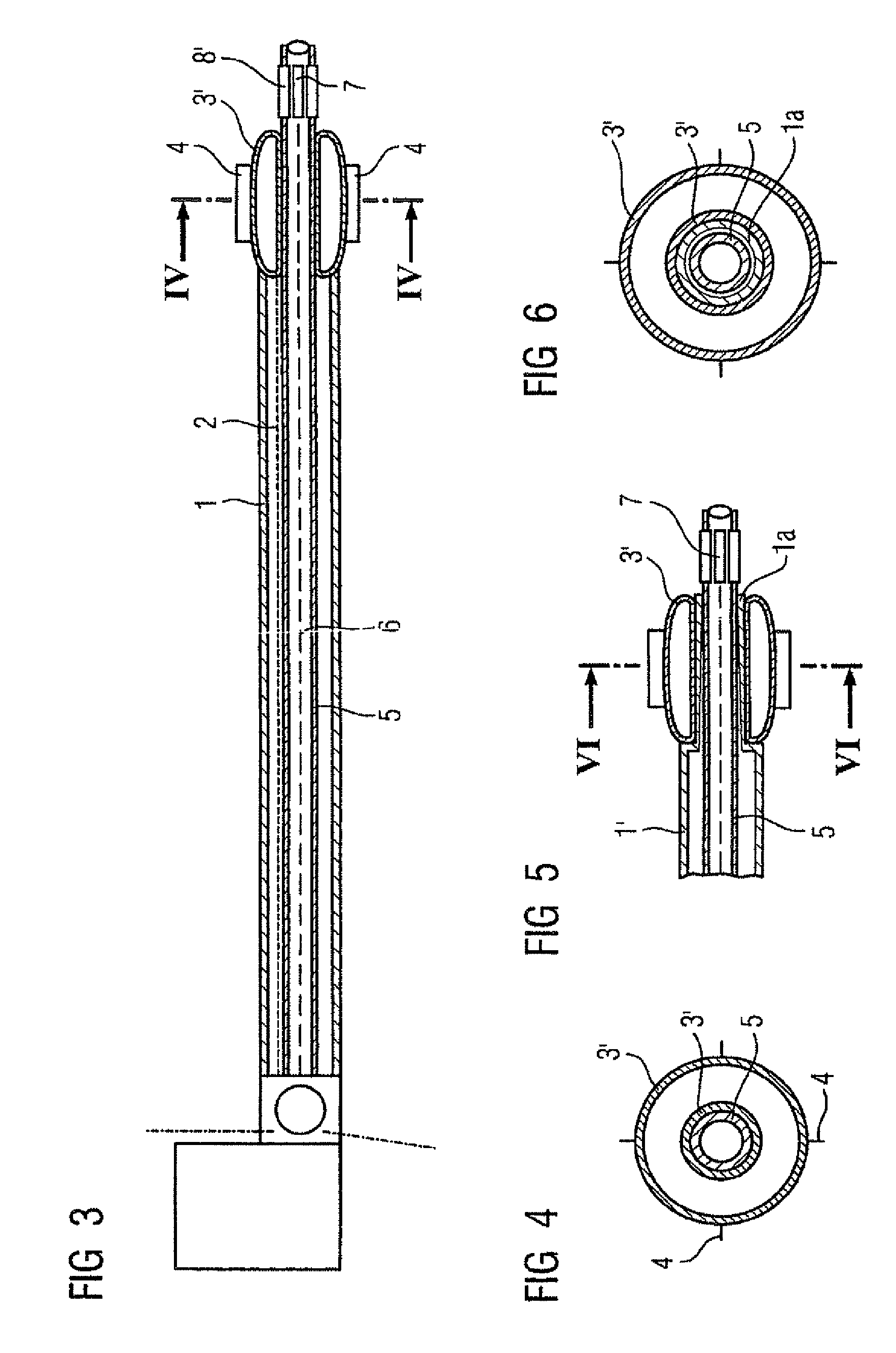
[0041]On the basis of FIG. 1 and 2 it is possible to identify, in a basic schematic diagram, the construction and functionality of the cutting-balloon catheter with integrated IVUS monitoring to be used for stenosis removal according to the invention. An inflation line 2 for inflating the cutting balloon 3 that is fastened at the distal end of the flexible catheter sheath 1, is disposed within said catheter sheath 1, with a plurality—in particular three or four—of cutting blades 4, being mounted on the outer surface of said cutting balloon and arranged in a manner essentially parallel to the axis. When the balloon is inflated these blades 4 make longitudinal incisions into the vascular deposits, or “shave” plaque from the vascular wall, before the coronary artery is dilated by the balloon.

[0042]In addition to the inflation line 2 the flexible catheter sheath 1 also accommodates a hollow flexible drive shaft 5 accommodating an IVUS signal line 6 for an IVUS sensor 7, said IVUS sensor...


PUM


Abstract

Device for implementing a cutting balloon intervention by means of a “cutting balloon” catheter, at the distal end of which is disposed an inflatable balloon with axially running blades mounted thereon, and which has IVUS monitoring, whereby the cutting balloon catheter is combined with an IVUS catheter to form an integrated module.

Description

CROSS REFERENCE TO RELATED APPLICATION[0001]This application claims priority of the German application No. 10 2004 015 639.5 DE filed Mar. 31, 2004, which is incorporated by reference herein in its entirety.FIELD OF THE INVENTION[0002]The invention relates to a device for implementing a cutting balloon intervention by means of a “cutting balloon” catheter, at the distal end of which is disposed an inflatable balloon with axially running blades mounted thereon, and which has IVUS monitoring.BACKGROUND OF THE INVENTION[0003]Vascular disease, in particular cardiac infarction, is one of the most common fatal illnesses. It is caused by disease of the coronary arteries (arteriosclerosis), in which the build-up of deposits (arteriosclerotic plaque) causes occlusions in the coronary arteries.[0004]Nowadays, if coronary angiography reveals serious stenoses in the coronary arteries, causing angina pectoris which restricts the patient's capability and / or puts the patient at risk, a PTCA (percu...

Claims


Application Information

Patent Timeline
Patent Type & Authority Patents(United States)
IPC IPC(8): A61B17/22A61B17/00A61B8/12A61B17/32A61B19/00A61D1/02A61F2/958A61M25/088
CPCA61B17/320725A61B2017/22061A61B2019/528A61B2090/3784
Inventor MASCHKE, MICHAEL
Owner SIEMENS HEALTHCARE GMBH
Why Eureka
Try Eureka