Lens array sheet, light source and liquid crystal display device

a liquid crystal display device and array sheet technology, applied in the field of lens array sheet, light source and liquid crystal display device, can solve the problems of difficult to convert the light from the light source into perfectly parallel light, difficult to adjust the array pitch of the pixels, and difficult to sufficiently suppress the moire fringes produced by the lens array layer, etc., to reduce the pattern of brightness uniformity, suppress the moire fringes, and improve the visibility of the liquid crystal display device

Active Publication Date: 2012-02-07
SATURN LICENSING LLC
View PDF22 Cites 3 Cited by
  • Summary
  • Abstract
  • Description
  • Claims
  • Application Information

AI Technical Summary

Benefits of technology

[0008]Though the liquid crystal display device described in JP-A No. 2000-206529 may reduce the effects of the moire fringes on visibility and the like, actually the moire fringes may appear. Moreover, it is difficult to adjust the array pitch of the pixels, since there is a need for modifying a design of the liquid crystal panel itself and a manufacturing line of the liquid crystal panel. Thus, a technique has been developed to suppress moire fringes per se from being produced.
[0011]Therefore, the present invention has been made in view of the above-mentioned issues, and it is desirable to provide a new and improved lens array sheet, light source and liquid crystal display device in which it is possible to suppress degradation of the image quality and reduce effects of moire fringes on the image quality.
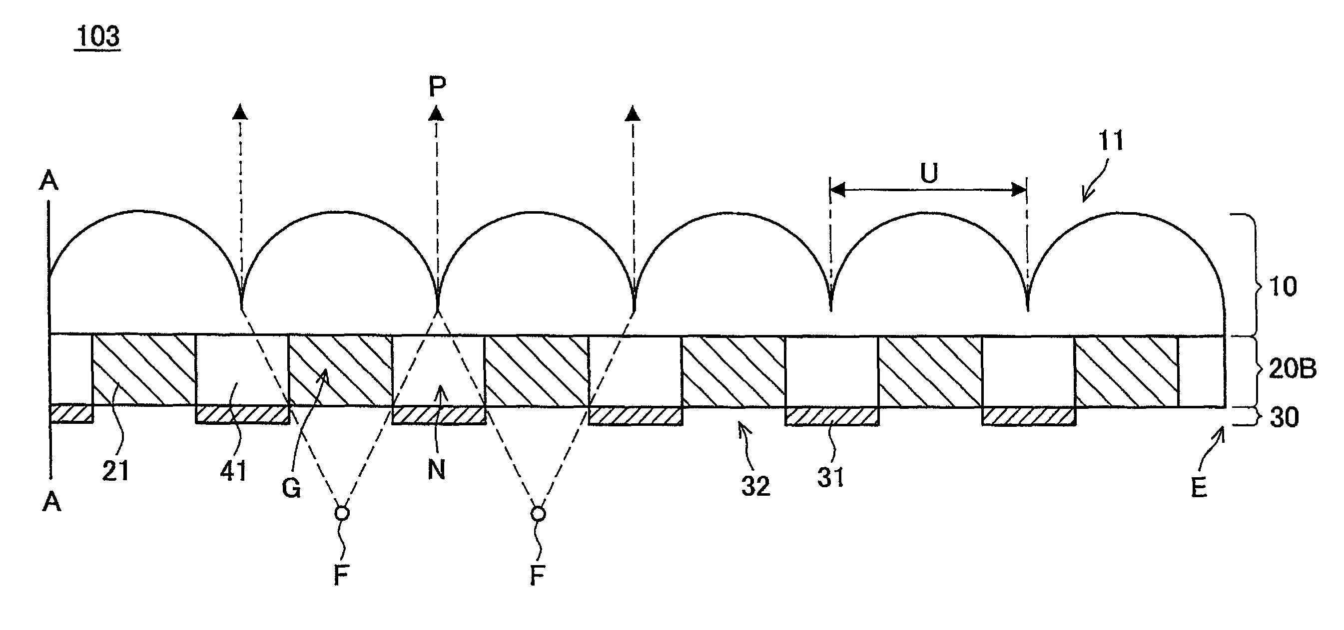
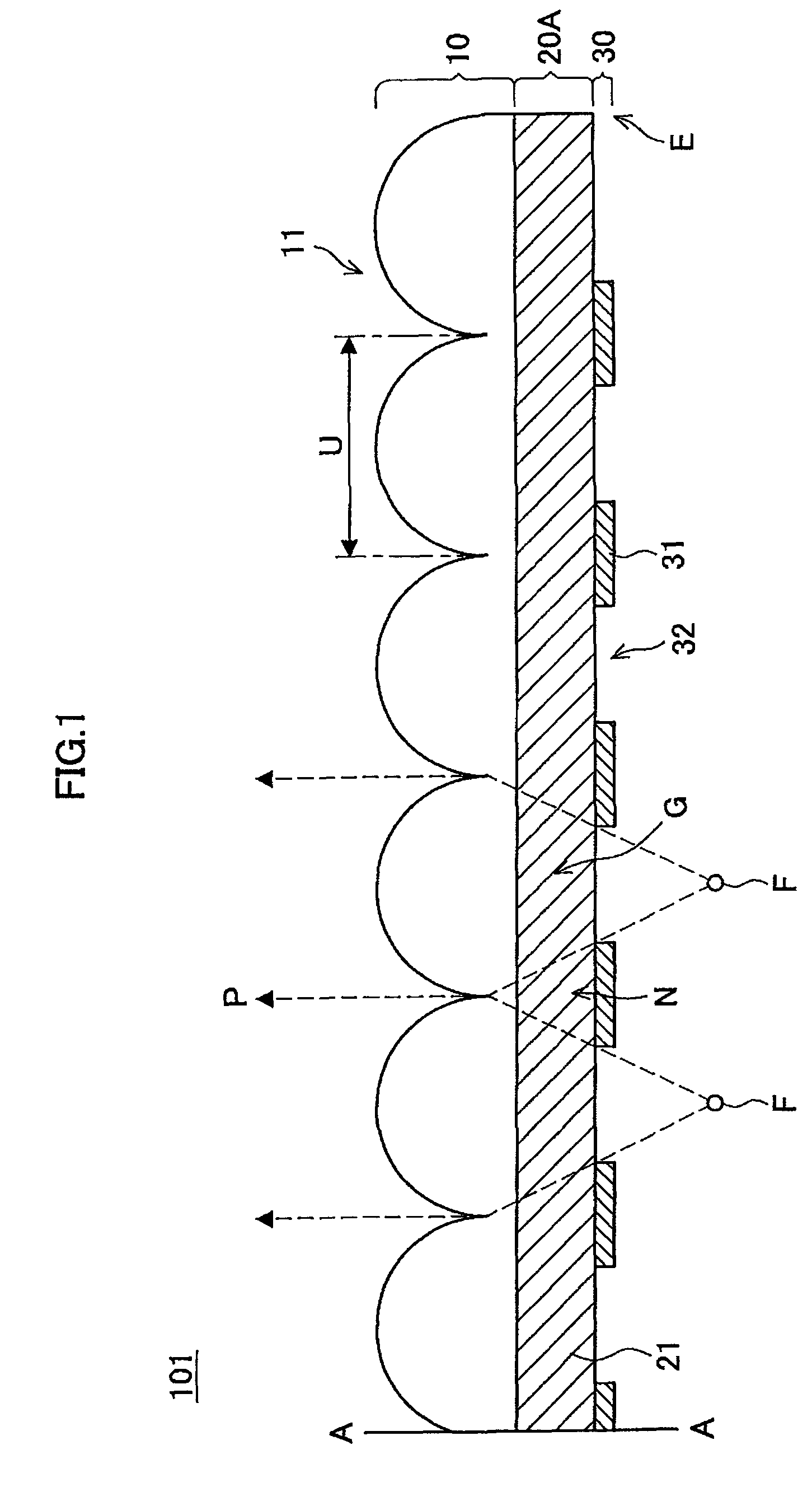
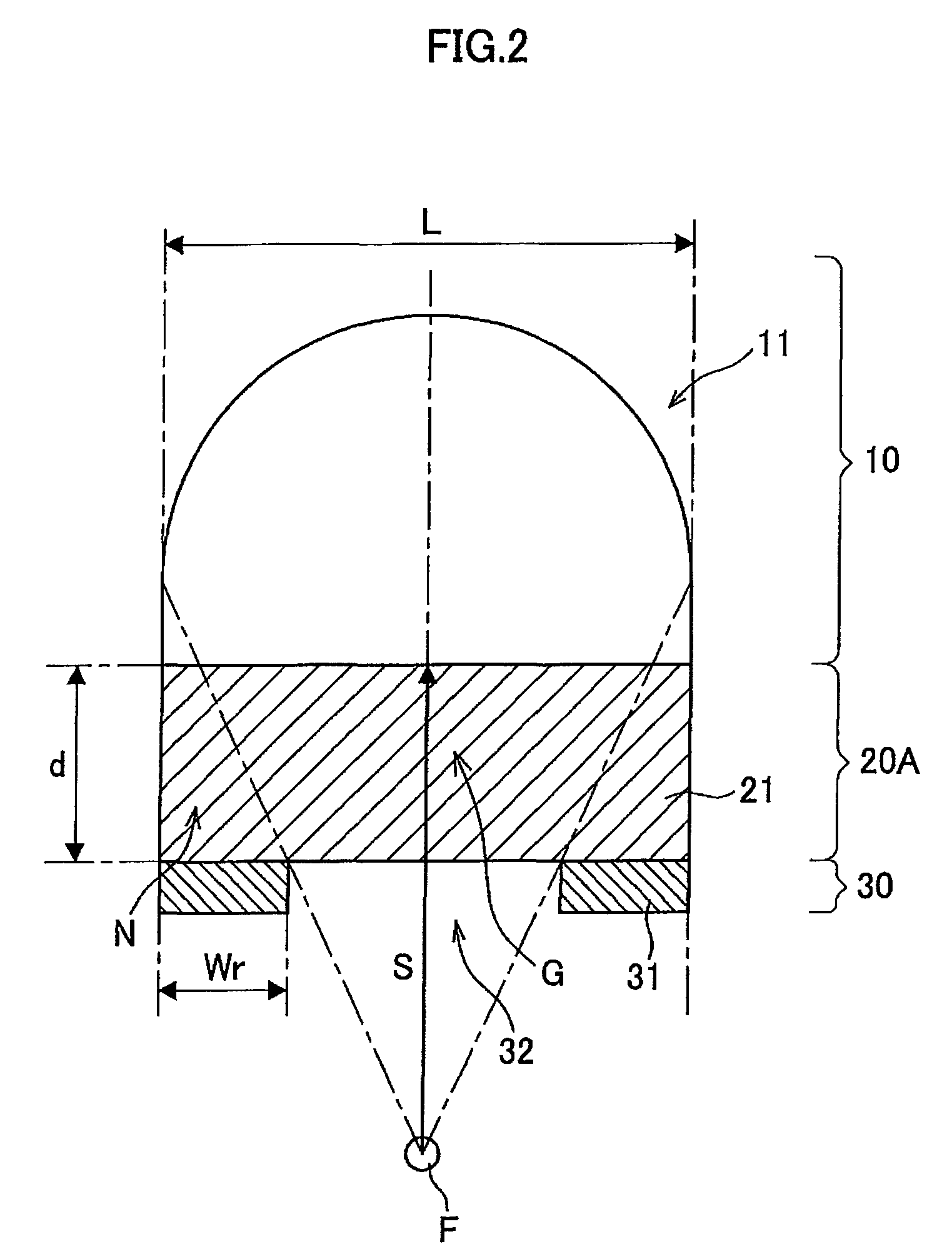
[0013]With this arrangement, light emitted from a side of the light reflection layer to the lens array sheet is in part reflected at the light reflection layer. In addition, a part of the light emitted to the light focusing region in the plurality of lenses passes through the opening. The light having passed through the opening is diffused by the light diffusion layer before the light reaches the lens layer. Then, the diffused light reaches the lens layer and converted into generally parallel light by means of the plurality of lenses. It is noted that the light to be converted into the generally parallel light is diffused. As a result, after conversion into the generally parallel light by means of the lenses, the light turns out to be the generally parallel light, while brightness change of the light between dark and light intensity due to an array pattern of the plurality of lenses in the lens layer is reduced.
[0027]According to the embodiments of the present invention described above, effects of moire fringes on the image quality can be reduced while suppressing the image quality being degraded.

Problems solved by technology

Moreover, it is difficult to adjust the array pitch of the pixels, since there is a need for modifying a design of the liquid crystal panel itself and a manufacturing line of the liquid crystal panel.
It is difficult, however, to sufficiently suppress the moire fringes from being produced using the lens array layer as described above.
In other words, since the lens array layer per se also has a regular structured pattern and the regular structured pattern has effects on the parallel light, it is difficult to convert the light from the light source into perfectly parallel light.

Method used


Image

  • Lens array sheet, light source and liquid crystal display device
  • Lens array sheet, light source and liquid crystal display device
  • Lens array sheet, light source and liquid crystal display device

Examples


example

[0158]First, lens array sheets 101 to 105 according to the first to fifth embodiments, respectively, and lens array sheets 201 to 204 according to the seventh to tenth embodiments, respectively, were created. In this case, a lens layer and a transparent portion contained in each of the lens array sheets were formed of an acrylic resin and a light diffusion portion is formed of an acrylic resin having silica dispersed therein. In addition, a light reflection layer was formed of a urethane resin mixed with a white pigment. A shape of each of configurations was configured such that a haze value of each of light diffusion layers was equal to 20%.

[0159]A liquid crystal display device 400 according to the eleventh embodiment, as shown in FIG. 14, was then created for each of the lens array sheets. In this case, a backlight 405 and a light diffusion plate 404 were implemented by a backlight and a light diffusion plate of KDL-40X5000 (trade name) contained in a liquid crystal television man...


PUM

PropertyMeasurementUnit
hazeaaaaaaaaaa
particle sizeaaaaaaaaaa
reflectanceaaaaaaaaaa

Abstract

A lens array sheet includes a lens layer having a lens surface on which a plurality of lenses are formed in an array, a light reflection layer arranged at an opposite side to the lens surface of the lens layer and having an opening within a light focusing region in the lenses to transmit light, for reflecting light at a site other than the opening, and a light diffusion layer arranged between the lens layer and the light reflection layer, for diffusing light, which passes through the opening and is directed toward the lens layer.

Description

BACKGROUND OF THE INVENTION[0001]1. Field of the Invention[0002]The present invention relates to a lens array sheet, a light source and a liquid crystal display device.[0003]2. Description of the Related Art[0004]Recently, a liquid crystal panel such as liquid crystal display device has been gradually enlarged. Although the liquid crystal panel may be enlarged, it is not allowed to degrade the image quality of the panel and it is demanded that high definition image quality of the panel can be achieved even for a large-scale screen. In order to achieve the high definition image quality for the large-scale screen, for example, it is strongly demanded that brightness of the screen can be maintained or improved, or viewing angle can be widened. In accordance with these demands, some techniques have been proposed to arrange a micro array lens in the liquid crystal panel and improve the brightness and the viewing angle of the liquid crystal panel. Arranging the micro array lens makes it p...

Claims


Application Information

Patent Timeline
Patent Type & Authority Patents(United States)
IPC IPC(8): G02F1/1335
CPCG02B3/0056G02B5/0236G02B5/0278G02B5/0294
Inventor OGASAWARA, TOYOKAZUMAEDA, TSUYOSHI
Owner SATURN LICENSING LLC
Why Eureka
Try Eureka