Energy-saving vehicle

a technology for vehicles and fuel tanks, applied in the field of vehicles, can solve the problems of high energy consumption and high energy consumption of vehicles, and achieve the effects of reducing the resistance of the pressure region, increasing the speed of the vehicle, and saving energy

Active Publication Date: 2012-02-14
ZHU XIAOYI
View PDF4 Cites 7 Cited by
  • Summary
  • Abstract
  • Description
  • Claims
  • Application Information

AI Technical Summary

Problems solved by technology

However, increase of weight also results in high energy consumption.
But an un-neglectable problem with them is that energy consumption thereof is still high after various transmission devices are used.

Method used


Image

  • Energy-saving vehicle
  • Energy-saving vehicle
  • Energy-saving vehicle

Examples


first embodiment

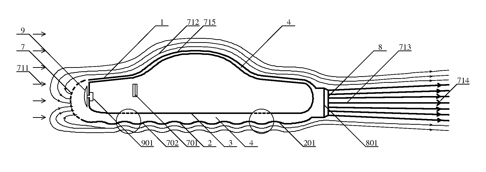
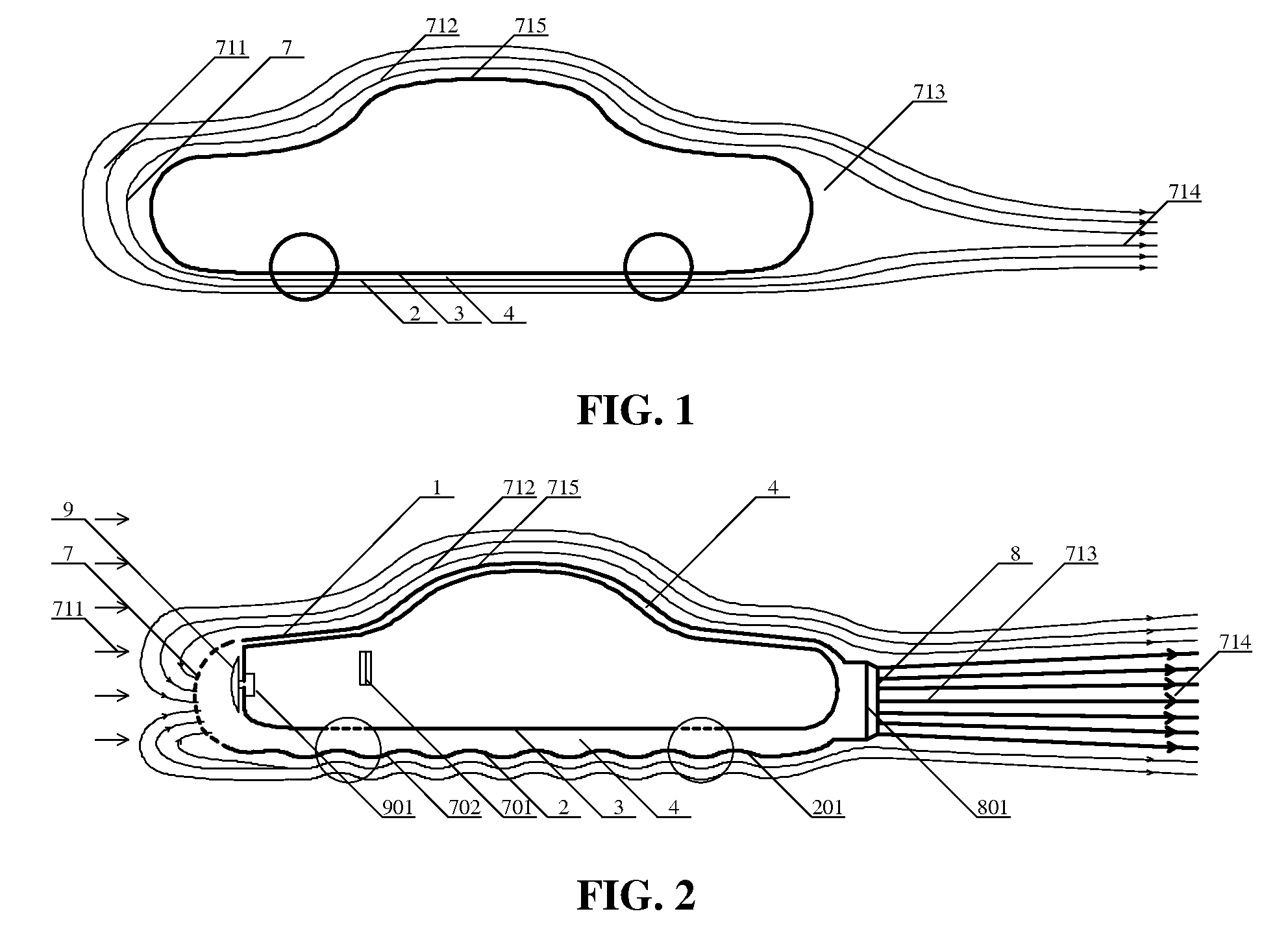
[0045]As shown in FIG. 2, an energy-saving vehicle of the invention comprises a housing comprising an outer portion 2 and an inner portion 3, an air-flow channel 4, a first air inlet 7, an air outlet 8. The first air inlet 7 is disposed in the front of the vehicle, the air outlet 8 is disposed at the back of the vehicle, and the air-flow channel 4 is disposed between the outer portion 2 and the inner portion 3 of the housing and connected to the air outlet 8. In this embodiment, the air-flow channel 4 is annular.

[0046]A rotating head 9 is disposed in the first air inlet 7 and driven by a motor 901. At least a third air inlet 701 is disposed around the vehicle and connected to the air-flow channel 4. A spoiler 201 in the shape of a concave-convex parabola is disposed at the bottom of the outer portion 2, and at least a second air inlet 702 is disposed on the spoiler 201. In this embodiment, the rotating head 9 is in the shape of a disk.

[0047]As the vehicle travels at a high velocity,...

second embodiment

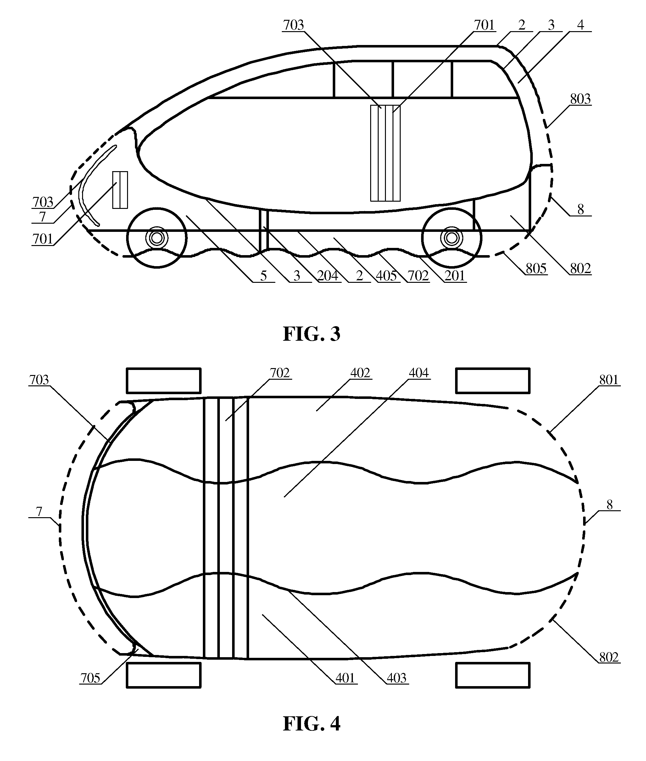
[0053]As shown in FIGS. 3-5, an energy-saving vehicle of the invention comprises a housing comprising an outer portion 2 and an inner portion 3, an air-flow channel 4, an airflow hole 5, a first air inlet 7, and an air outlet 8. The air-flow channel 4 is disposed between the outer portion 2 and the inner portion 3 of the housing. In this embodiment, the air-flow channel 4 is circular. The airflow hole 5 can be regarded as a bottom air-flow channel that has a same width as the housing. The bottom air-flow channel is divided into three independent sub-air-flow channels by two spoilers 403, and thus four sub-air-flow channels are formed. The first air inlet 7, a middle air-flow channel 404 and the air outlet 8 are sequentially connected. A left air inlet 7, an air-flow channel 402 and a rear air outlet 801 are sequentially connected. A right air inlet 7, an air-flow channel 401 and a rear air outlet 802 are sequentially connected.

[0054]At least a third air inlet 701 is disposed in the ...

third embodiment

[0069]As shown in FIGS. 6 and 7, an energy-saving vehicle of the invention comprises a housing comprising an outer portion 2 and an inner portion 3, windshield 5, a door 6, a first air inlet 7, an air-flow channel, a pair of first air outlets 801 and a second air outlet 803. The first air outlets 801 are disposed on both sides of the bottom at the back of the vehicle, and the second air outlet 803 is disposed at the center of the back of the vehicle. The air-flow channel is formed between the outer portion 2 and the inner portion 3, and comprise a first sub-air-flow channel 4 and a second sub-air-flow channel 401 connected to each other. The first sub-air-flow channel 4 is linear, and the second sub-air-flow channel 401 is annular.

[0070]A rotating head 705 is disposed at the center of the first air inlet 7 and driven by a motor 706. The rotating head 705 is in the shape of a cone, a flying plate, a hemisphere, a stream line and so on. The rotating head 705 generates centrifugal forc...


PUM


Abstract

An energy-saving vehicle, has a housing including an outer portion, an inner portion, an air-flow channel, at least a first air inlet, and at least an air outlet, a pair of front wheels, a pair of rear wheels, and a steering wheel. The air-flow channel is disposed between the outer portion and the inner portion of the housing. The first air inlet is disposed in the front of the vehicle The air outlet is disposed at the back of the vehicle, The first air inlet and the air outlet are connected to the air-flow channel. The front wheels and the rear wheels are driven by a power unit. The length of the air-flow channel is no less than that of the upper portion of the housing. As the vehicle travels at a high velocity, air is led in from the air inlet and sprayed from the back of the vehicle, instantly filling a low pressure region at the back of the vehicle and turning the back of the vehicle into a high pressure region, which saves energy. Moreover, since the length of the air-flow channel is larger than that of the upper portion of the housing, lift resistance is eliminated, and the vehicle travels more stably.

Description

CROSS-REFERENCE TO RELATED APPLICATIONS[0001]This application is a continuation-in-part of International patent application No. PCT / CN2008 / 073367 with an international filing date of Aug. 31, 2007, designating the United States, now pending, and further claims priority benefits to Chinese patent application No. 200810000302.3 filed Jan. 7, 2008, Chinese patent application No. 200810008130.4 filed Feb. 13, 2008, Chinese patent application No. 200710186155.9 filed Dec. 27, 2007, Chinese patent application No. 200810068379.4 filed Jul. 11, 2008, and Chinese patent application No. 200710186156.3 filed Dec. 27, 2007. The contents of all of the aforementioned applications, including any intervening amendments thereto, are incorporated herein by reference.BACKGROUND OF THE INVENTION[0002]1. Field of the Invention[0003]The invention relates to a vehicle, and more particularly to an energy-saving vehicle.[0004]2. Description of the Related Art[0005]For vehicles, upward resistance occurs duri...

Claims


Application Information

Patent Timeline
Patent Type & Authority Patents(United States)
IPC IPC(8): B60J7/00
CPCB61D17/02B62D35/00B62D35/02B63B1/36Y02T30/32Y02T70/121Y02T10/82Y02T10/88Y02T30/00Y02T70/10
Inventor ZHU, XIAOYI
Owner ZHU XIAOYI
Why Eureka
Try Eureka